14 Unidrive SP Low Voltage DC Installation Guide
www.controltechniques.com Issue Number: 1
4.6 System configurations
The following diagrams show different system configurations for a Unidrive SP
operating from a Low Voltage DC supply.
The choice of system configuration depends on the amount of regen energy the DC
supply can absorb.
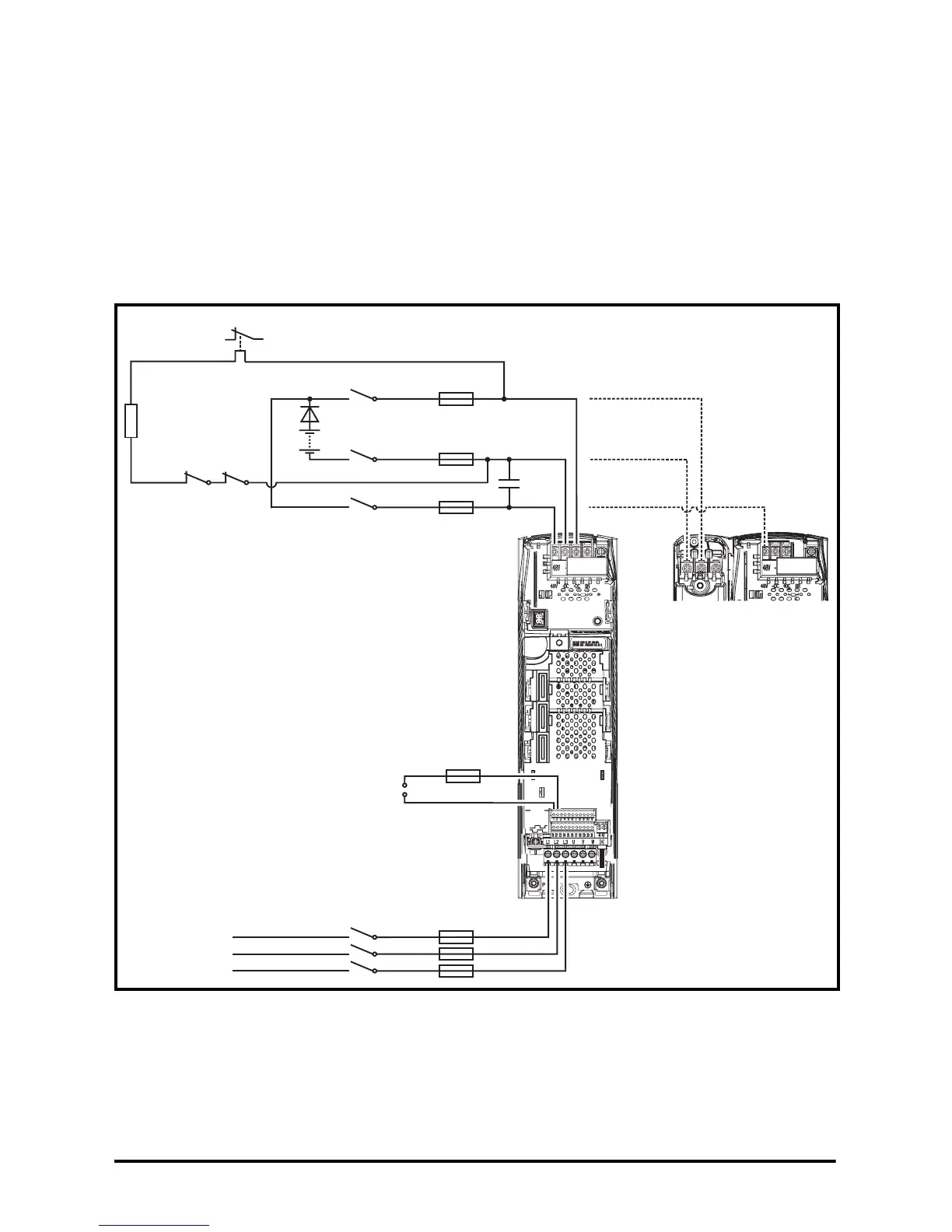
4.6.1 System configuration 1
This system configuration is suitable for systems were the power supply cannot absorb
any energy from the load through the drive, hence the reason for blocking diode D1
being fitted in series with the DC supply.
Figure 4-1 System configuration 1 circuit diagram for Unidrive SP size 1 to 3
*C1 is only required with Unidrive SP size 1
See Chapter 5 Component data on page 30 for details on components.
F1a
3-phase
AC supply
K1
F2a
F2b
F2c
K2c
K2b
K2a
C1*
Rdis
PS1
D1
K1b K2d
-DC
48V
+DC
L1
L2
L3
48V
DC1/-DC
DC2/+DC
Size 2 and 3
connections
F3
T2
T1
Ovld.1
Aux.1
Control + 24V
external input