20 Unidrive SP Low Voltage DC Installation Guide
www.controltechniques.com Issue Number: 1
4.6.5 System configuration 2
This configuration is suitable for systems where the drive may be expected to absorb
energy from the load at drive rated current (including overload current if applicable), and
dissipate this energy into a brake resistor. However, further consideration is required
when using a brake resistor in Low Voltage DC mode.
As the DC bus voltage varies the motor power available varies in proportion to the
voltage but the power that may be dissipated in a brake resistor varies with the square
of the voltage. To enable the maximum brake power to match that from the motor in Low
Voltage DC mode, the brake resistor value must be reduced in proportion to the voltage.
The arrangement shown in the circuit below automatically connects the appropriate
brake resistor depending on the supply voltage. Note that the brake resistor thermal
overload devices are also connected to the supply selection interlocks. If either resistor
overheats, then the Low Voltage DC and AC supplies are both tripped off. As shown in
Figure 4-6 Control circuitry for system configuration 2 on page 21
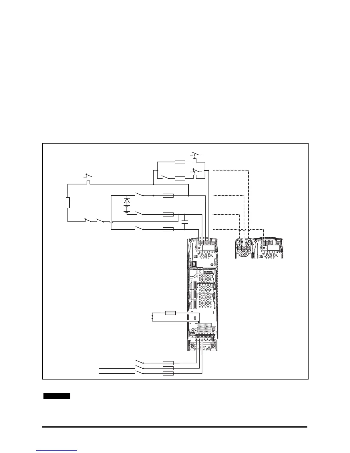
Figure 4-5 System configuration 2 circuit diagram for Unidrive SP size 1 to 3
*C1 is only required with Unidrive SP size 1
See Chapter 5 Component data for details on components.
F2a
F2b
F2c
C1*
Rdis
PS1
D1
K1b K2d
-DC
48V
+DC
48V
DC1/-DC
DC2/+DC
Size 2 and 3
connections
Brake
Brake
F1a
3-phase
AC supply
K1
L1
L2
L3
F3
T2
T1
K2c
K2b
K2a
Aux.1
Ovld.1
R_LVDC
K2f
R_norm
Aux.3
Aux.2
Ovld.3
Ovld.2
Control + 24V
external input
The total brake resistance used in Low Voltage DC mode is the parallel configuration of
R_ LVDC and R_norm.
NOTE