24 Unidrive SP Low Voltage DC Installation Guide
www.controltechniques.com Issue Number: 1
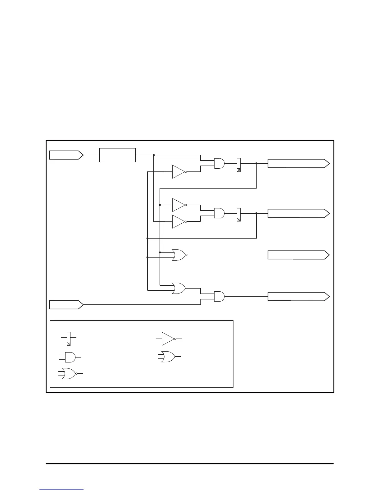
4.7 Power circuit control logic and sequencing
Control logic is required to interlock and sequence the contactors set out in section
4.6 System configurations on page 14 to ensure correct operation. This can be
accomplished using relays and timers or an SM-Applications option module.
Figure 4-9 shows the basic logic that is required. The logic provides the following
functions:
• Change-over delay.
• Prevention of both supplies being connected to the drive at the same time.
• The discharge contactor is closed when neither supply is connected.
• Automatic change over of the supply if the AC supply fails, or change-over by switch
selection.
• The drive is disabled when neither supply is connected.
Figure 4-9 Control logic diagram
*Supply loss detection signal could also be the output of a supply selector switch (Low
Voltage DC or nominal AC supply).
AC supply
loss detection*
Drive enable
AC supply
Delay
on t2
Drive enable
Close AC contactor
Close DC contactor
Close discharge contactor
Delay
on t1
Key:
Timer coil, delay ON
Logic AND gate
Logic NOT gate
Logic OR gate
Logic NOR gate