Unidrive SP Low Voltage DC Installation Guide 39
Issue Number: 1 www.controltechniques.com
Safety Information Introduction Product information System design
Component data
Index
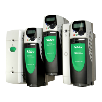
Figure 5-4 575V/690V drive time vs current fuse characteristic specification
5.5 Blocking diode (D1)
The blocking diode D1 is used to prevent energy from being returned into the Low
Voltage DC supply.
Table 5-8 D1 specification
A suitable supplier for the above diode can be Semikron™ with the SKKE isolated base
module diode. The diode must be mounted on a suitable heatsink. See manufacturer
data for heatsink requirements of the device.
5.6 Supply capacitor (C1)
Table 5-9 C1 specification
0.01
0.1
1
10
100
Drive voltage rating
(V)
Diode type
Working current
(A)
Voltage rating
(V)
200
Standard recovery
3 x drive output
current rating
600
400 1200
575
1500
690
Suitable capacitor
type
Capacitor value
(nF)
Voltage rating
(V)
Metalised polyester 100 ≥250
This capacitor is only required with the Unidrive SP size 1. The capacitor should be
connected directly to the drive terminals.
NOTE