22 Unidrive SP Low Voltage DC Installation Guide
www.controltechniques.com Issue Number: 1
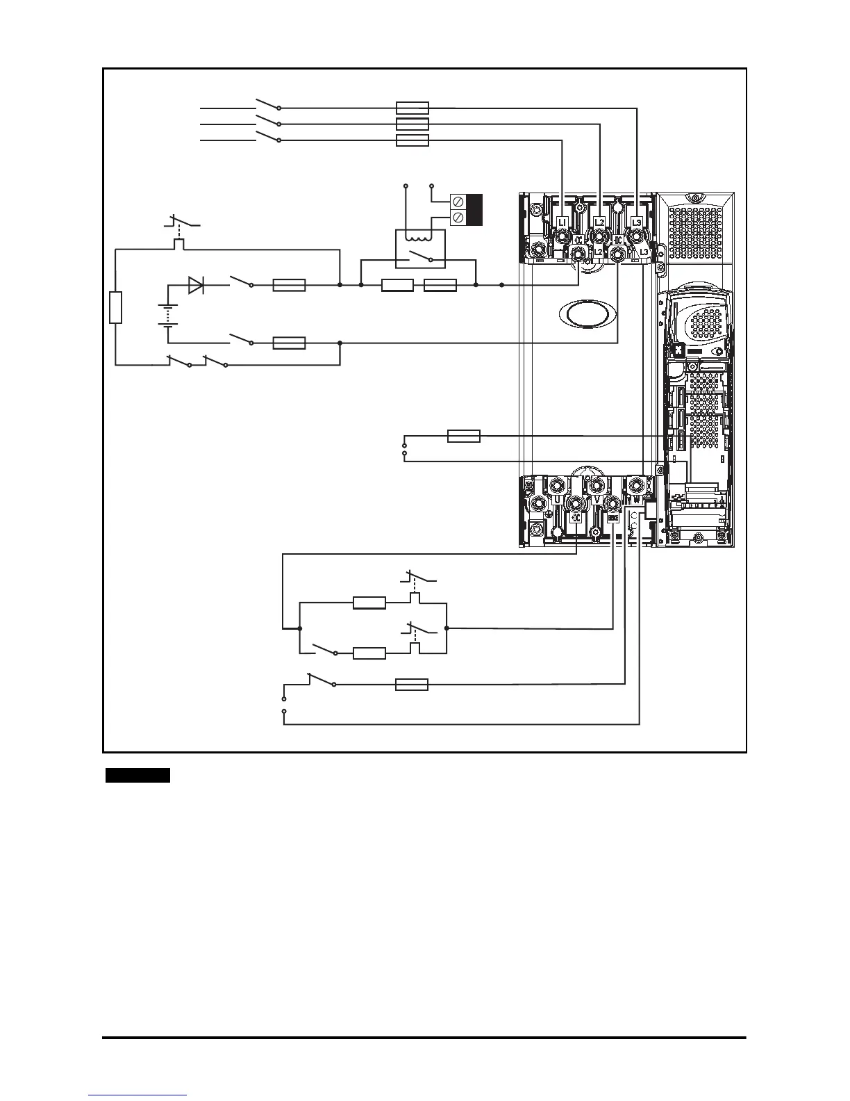
Figure 4-7 System configuration 2 circuit diagram for Unidrive SP size 4 to 6, SPMA/D
See Chapter 5 Component data on page 30 for details on components.
See section 4.8 External soft start circuit control on page 27 for external soft start circuit
control.
The total brake resistance used in Low Voltage DC mode is the parallel configuration of
R_ LVDC and R_norm.
F2d
K1a
24V Low voltage DC
mode enable (T51)
0V (T50)
Brake
F3
T1 T2
-DC
+DC
F2a
F2b
K2b
K2a
Rdis
PS1
D1
K1b K2d
Rs
41
42
F1a
3-phase
AC supply
K1
L3
L2
L1
24V
RLY1
Drive
terminals
R_LVDC
K2f
R_norm
Aux.3
Aux.2
Ovld.3
Ovld.2
F4
Aux.1
Ovld.1
Control + 24V
external input
24V
NOTE