Connection diagram
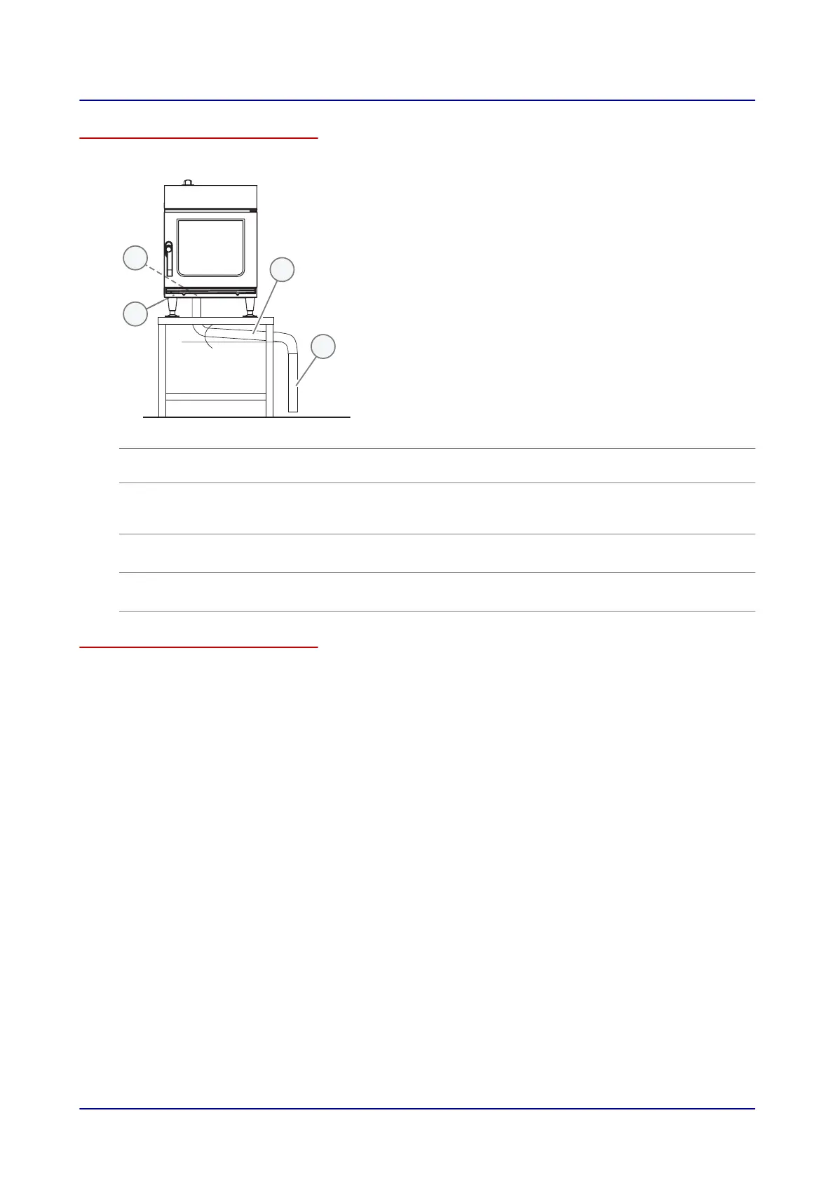
The figure below shows a size 6.10 mini combi oven used as an example representing all models:
No. Designation Function
1
Drain Connection At the back of the unit, connection point C – please refer to 'Connec‐
tion drawing' on page
64
2
Safety overflow
■
At the bottom of the unit, connection point M – please refer to
'Connection drawing' on page 64
■
Used to drain water in the event of a failure (blockage)
3
1½" drain pipe
■
Minimum inner diameter = 1½"
■
Downward slope: min. 5% (3°)
4
1½" (2") drain pipe
■
Minimum inner diameter = 1½" (2")
■
Downward slope: min. 5% (3°)
Installing the drain connection
Connect the unit as shown in the connection diagram.
6 Installation
Installation Manual 50