Rear view Key
A Water connection (soft water (filtered), for wa‐
ter injection)
B Water connection (cold water (unfiltered), for
cleaning)
C Drain connection 1.5”
D Electrical connection
E Bonding
F Rinse-aid connection
G Cleaning-agent connection
H
Air vent Æ 1.18"
I
Ventilation port Æ 1.69"
M Safety overflow 2.36" x 0.79"
N RJ45 Ethernet port
P mini Condensation Hood Pro - optional
Q Used to reset the thermal cutout
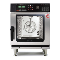
mini 6.10 dimensions and connection points (right-hinged unit door)
Front view Side view
View from above with wall clearances Connections at bottom of unit
2
2
2
I
H
20.4
90°
5.7
23
19.2
19.1
49.8
2.6
5.2
M
A
B
C
FG
1.2
3.3
73
14.6
16.5
2
1.8
0.9
1
1.5
22.43.5
1
4.7
1.7
16.9 1.7
E
N
D
4.4
10 Connection drawings
Installation Manual 65