ProLine 124-221-321-324 Operator manual 105
UK
4. MOUNTING
ProLine 321 - 324
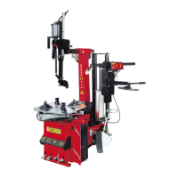
- Remove the side cover (fig.5A).
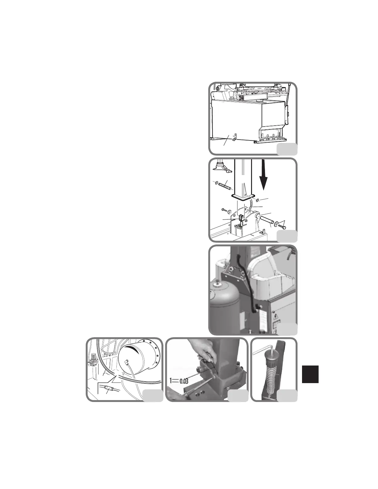
- Insert the air hose G (fig. 5B) into hole A behind
the pole tilting cylinder.
- Insert hose G1 (Fig. 5C) into the rear connection
(Proline 324)
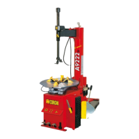
- Apply pin B into hole C and fasten (tightening
torque 70Nm) with screws and washers D (Fig. 5A).
- Insert pin E into hole F and into the U-bolt of
the pole tilting cylinder, and fasten with Circlip
M (Fig. 5A).
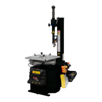
- Connect pipe G (Fig. 5D) to the intermediate
union connected to the pole lifting tap H (Proline
321).
- Adjust the position from both sides of the
column. The clearance between the screw head
and the side of the column must be 0.03 mm
(fig.5E) and tighten the screws
- Undo the screw of the spring stop knob and
insert the spring contained in the packaging.
Fasten the knob using the previously unscrewed
screw. (fig.5F).
- Fit the hose connector of tank 2 into hose Q,
fasten the tank 2 to the machine with nuts and
washers R, and tighten the clamp O onto the
hose Q (fig. 5G) (T.I. version only).
A
D
G
M
C
B
E
F
5B
5A
No.
5C
5D
G
H
5E 5F