Cosman G4 Radiofrequency Generator Service Manual (SPI 11291 Rev A)
9.1.1 Additional Example Screens
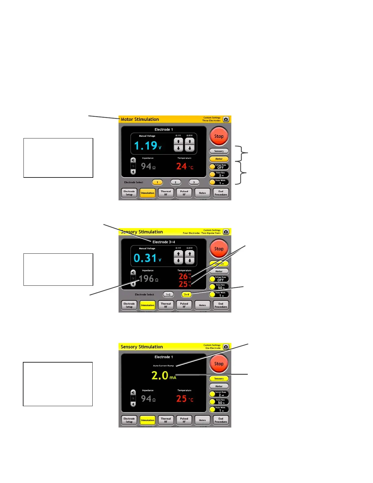
The One Touch Stimulation screen will appear differently depending on the current settings:
• Electrode Setup settings (see Section 7.1)
• Stimulation Mode: Sensory or Motor
• Auto Ramp Setting: Off/Manual or On/Auto (see Section 9.1.2)
• Control Units setting: Voltage- or Current-controlled output (see Section 9.1.2)
Sensory
Stimulation Mode
Two Bipolar Pairs
Sensory
Stimulation Mode
One Electrode,
uto Ramp = On &
ni
=
rr
n
Bipolar readings:
Voltage/Current and Impedance
between the two electrodes in
the bi
olar
ai
Motor Mode
Indicator
Motor Stimulation
Mode
Three Electrodes
Mode: Select Sensory
or Motor Stimulation
output
Settings Panels:
Mode switches
between Sensory &
Motor settings
Electrode Panel (Black area):
Displays all readings for the
indicated bipolar electrode pair,
e.g. “Electrode 1+2”.
Temperature Readings:
One Temperature reading
from each electrode in
bipolar pair. For instance,
“E1” indicates a reading
from Electrode 1.
Electrode Select Buttons:
Select between bipolar
electrode pairs 1+2 or 3+4.
uto Ramp & Units
Indicator: Reads “Auto” if
uto Ramp=On, and
“Manual” otherwise.
Reads “Voltage” or
“Current” to match the
Control Units setting.
Output Level Reading:
Shown here in units of
Current (mA). This is
determined by the
Control Units = Current.
Output Increment &
Decrement Buttons:
bsent if Auto Ramp = On.
Electrode Select Buttons:
bsent when Electrode Setup
for one electrode or one
bipolar pair.
Section 9