It
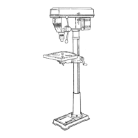
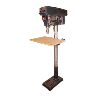
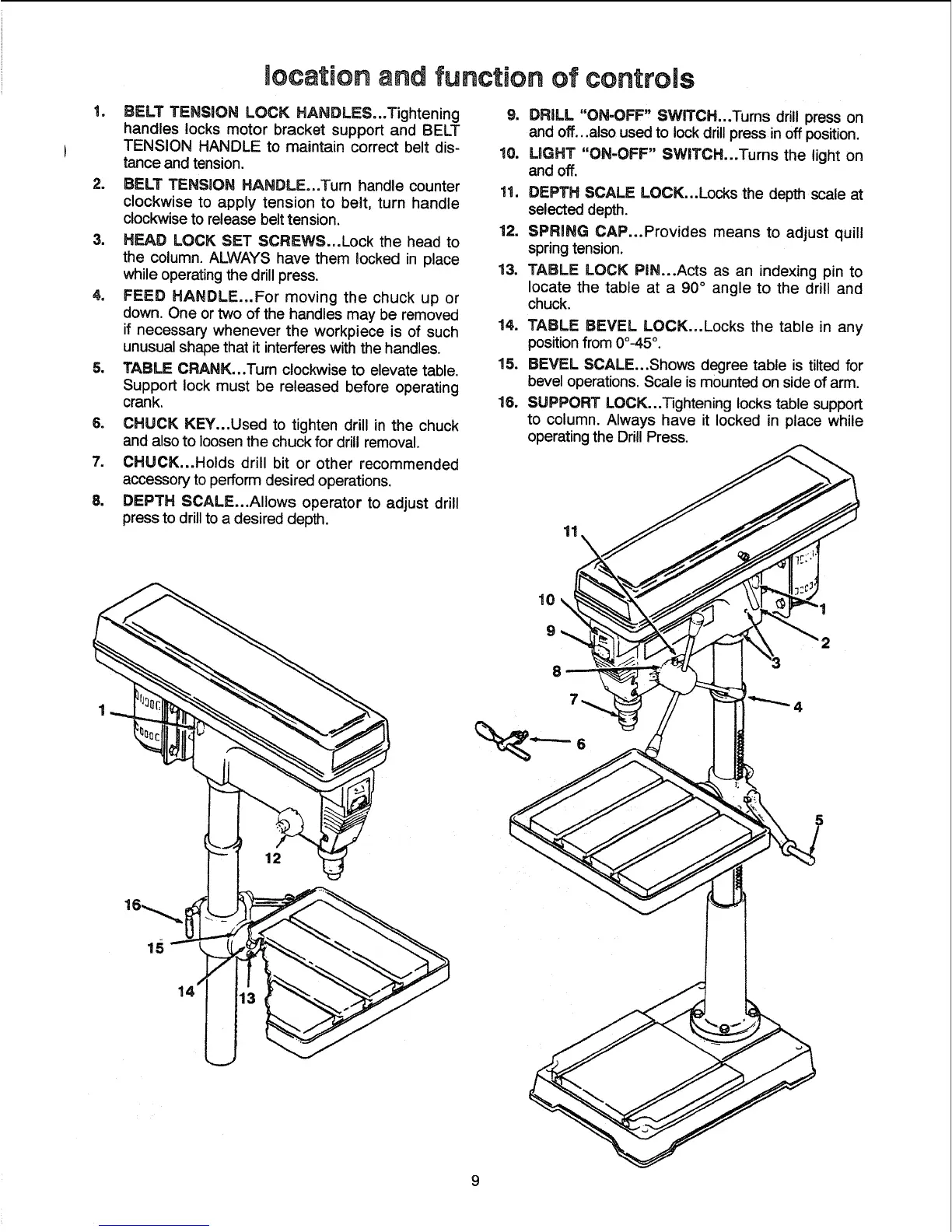
location and function of controls
BELT TENSION LOCK HANDLES...Tightening
handles locks motor bracket support and BELT
TENSION HANDLE to maintain correct belt dis-
tance and tension.
2. BELT TENSION HANDLE...Turn handle counter
clockwise to apply tension to belt, turn handle
clockwise to release belt tension.
3. HEAD LOCK SET SCREWS...Lock the head to
the column. ALWAYS have them locked in place
while operating the drill press.
4. FEED HANDLE...For moving the chuck up or
down. One or two of the handles may be removed
if necessary whenever the workpiece is of such
unusual shape that it interferes withthe handles.
5. TABLE CRANK...Tum clockwise to elevate table.
Support lock must be released before operating
crank.
6. CHUCK KEY...Used to tighten drill in the chuck
and also to loosen the chuck for drill removal.
7. CHUCK...Holds drill bit or other recommended
accessory to perform desired operations.
8. DEPTH SCALE...AIIows operator to adjust drill
press to drill to a desired depth.
9. DRILL "ON-OFF" SWITCH...Tums drill press on
and off...also used to lock drill press in off position.
10. UGHT "ON=OFF" SWITCH...Turns the light on
and off.
11. DEPTH SCALE LOCK...Locks the depth scale at
selected depth.
12. SPRING CAP...Provides means to adjust quill
springtension.
13. TABLE LOCK PIN...Acts as an indexing pin to
locate the table at a 90 ° angle to the drill and
chuck.
14. TABLE BEVEL LOCK...Locks the table in any
position from 0o-45°.
15. BEVEL SCALE...Shows degree table is tilted for
bevel operations. Scale is mounted on side of arm.
18. SUPPORT LOCK..,Tightening locks table support
to column. Always have it locked in place while
operating the Drill Press.
11
 Loading...