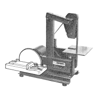
• • :{/:_"i:iii::i::(;:}:_;_:/ &: 'ii}&ii}}_
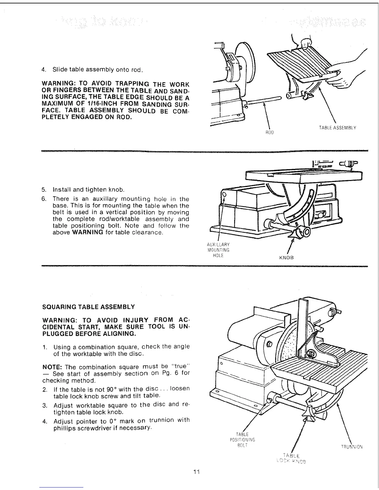
4. Slide table assembly onto rod,
WARNING: TO AVOID TRAPPING THE WORK
OR FINGERS BETWEEN THE TABLE AND SAND-
ING SURFACE, THE TABLE EDGE SHOULD BE A
MAXIMUM OF 1/16-INCH FROM SANDING SUR-
FACE. TABLE ASSEMBLY SHOULD BE COM-
PLETELY ENGAGED ON ROD.
:ROD
\
TABLE ASSEMBLY
.
6,
Install and tighten knob.
There is an auxiliary mounting hole in the
base, This is for mounting the table when the
belt is used in a vertical position by moving
the complete rod/worktable assembly and
table positioning bolt, Note and foltow the
above WARNING for table clearance,
AbXJLLAR_,
MOUNTING
HOL__
XNOB
SQUARING TABLE ASSEMBLY
WARNING: TO AVOID INJURY FROM AC.
CiDENTAL START, MAKE SURE TOOL IS UN.
PLUGGED BEFORE ALIGNING.
1. Using a combination square, check the angle
of the worktable with the disc.
NOTE: The combination square must be "true"
-- See start of assembly section on Pg. 6 for
checking method.
2. tf the table is not 90 ° with the disc,., loosen
table lock knob screw and tilt table,
3. Adjust worktable square to the disc and re-
tighten table lock knob.
4, Adjust pointer to 0 ° mark on trunnion with
phillips screwdriver if necessary,
1l
/
TABLE