Snack / Refreshment Center Setup and Operator's Guide
Page 71670001 April, 1999
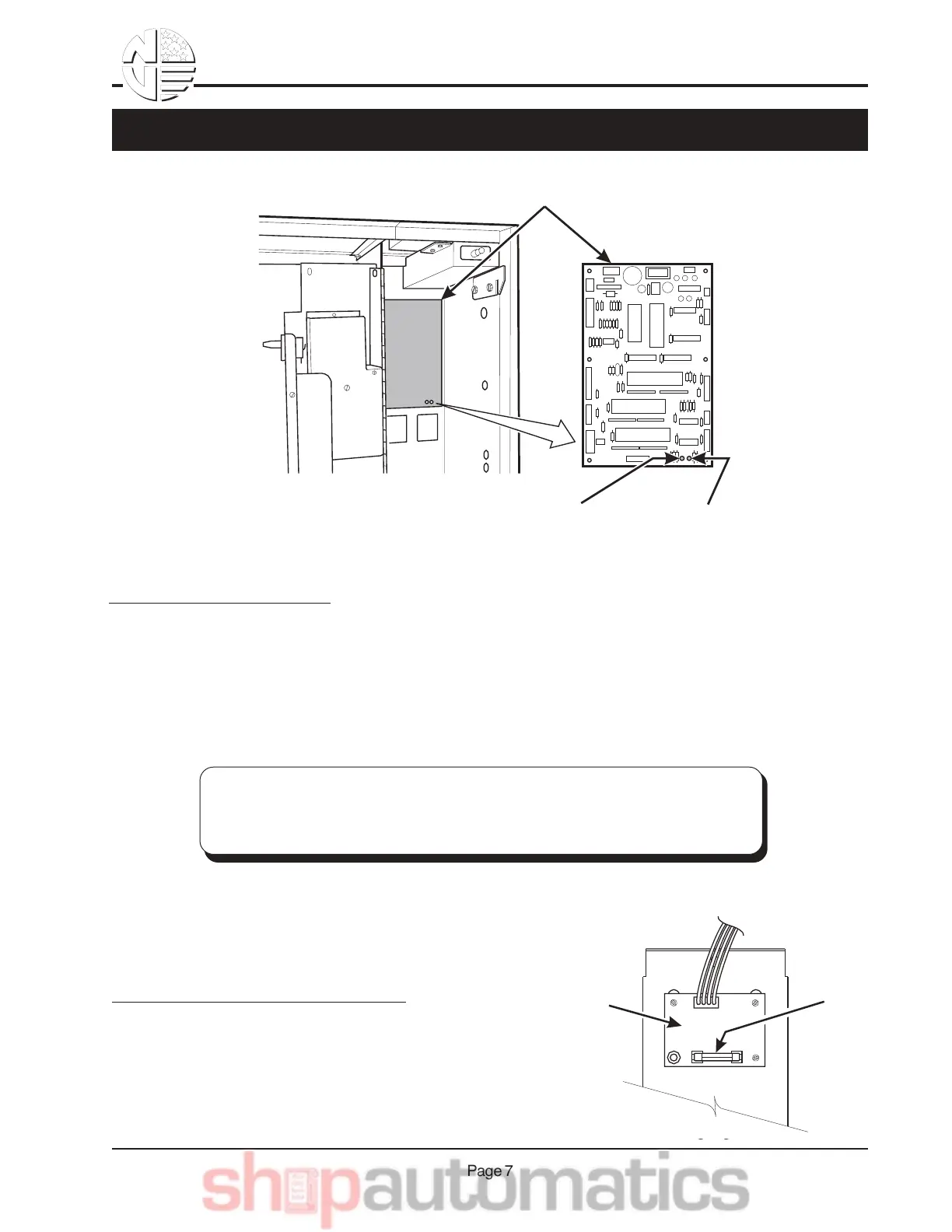
LED1 LED2
MAIN CONTROLLER
PCB ASSEMBLY
POWER ON
(L.E.D. 1)
FLASHING
HEARTBEAT
(L.E.D. 2)
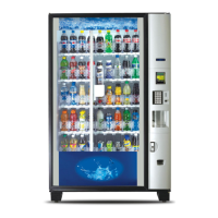
DC POWER
SUPPLY PCB
FOR COIN MECH
˜
AGC 1
FUSE
1 AMP
TOP
Back Side of U.S./Canada Power Panel. The
circuit board mounted on the rear of the power
panel is a dc power supply for the coin mecha-
nism. A fuse protects the board circuitry in the
event of a coin mechanism solenoid failure. If the coin
mechanism is not working, check this fuse. If the fuse is blown, a
bad coin mechanism solenoid could be at fault.
Main Controller PCB Display. This display consists of two light emitting diodes (LED) mounted on the
controller PCB.
POWER ON When lit, this red LED indicates electrical power is applied to
(L.E.D. 1) the controller PCB.
HEARTBEAT When flashing, this red LED indicates that the controller PCB is
(L.E.D. 2) active, and the software is operating.
NORMAL CONDITIONS:
When the merchandiser is operating normally, you should see a steady red
POWER ON indicator and a flashing red HEARTBEAT indicator. Contact a
service representative if any other condition exists.
6",-%"7.& 1,8& 9,8*21-"%.& : 2",-*,)$8;