Snack / Refreshment Center Setup and Operator's Guide
Page 40April, 1999 1670001
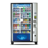
AIR DUCT
SHUTTER
SCREW
AIR
DISCHARGE
VENT
Refrigeration Module
Complete the setup of chilled snack features (models 764, 475, 787, 788, and 789):
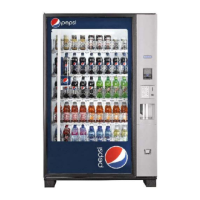
METHOD 2:
CONDENSATE
PAN
TO
EXTERNAL
DRAIN
DRAIN TUBE
(½ ID)
1. Connect a drain tube to the condensate pan.
2. Route the drain tube to an external drain or to
an overflow bucket.
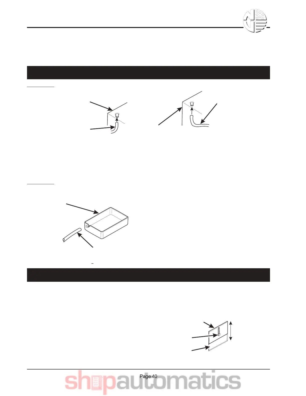
1. Remove the condensate drain tube from the
refrigeration module.
2. Connect a new drain tube to the refrigeration
module housing.
3. Route the new tube to an external drain or to
an overflow bucket.
REFRIGERATION
MODULE HOUSING
CONDENSATE
DRAIN TUBE
TO
CONDENSATE
PAN
NEW DRAIN TUBE
(½ ID)
REFRIGERATION
MODULE HOUSING
TO EXTERNAL
DRAIN OR
OVERFLOW
BUCKET
METHOD 1:
CAUTION
Do not close off all discharge vents. Doing so can
damage the refrigeration unit.
The air discharge and return vents are located in the right front and rear side wall. The vents are ad-
justed by loosening the screw and sliding the air duct shutter up or down as required. With the shutter
all the way up, the vent is fully open. The vent is closed when the shutter is all the way down. Ideally,
the temperature at the top tray should be the same as that
at the bottom tray. Using a thermometer to monitor tem-
perature, adjust the air discharge and return vents until the
temperatures are as close together as possible.
JB&& 6",,$2-&1&'$V%*D$ %1 -* ",& 5"8)7$&-"&1,& HW-$%,17& E%1*,&:"0-*",17;
OB&&J8X).-&-4$&J* %&E*.241%D$&1,8&'$-)%,&M$,-.&:64*77$%&>,7F;