Chapter 1: Introduction
12
1.5.3 Local Setup and Configuration
DIP Switches A switch -12 pole, B switch - 2 pole
Console Port local VT-100 terminal connection
1.5.4 RS-232 Console Port
Port interface V.24/RS-232 asynchronous, DCE
Port connector DB9F
Data rate (*default) 19200 bps
Data format -One start bit
-8 data bits
-No parity
-One stop bit
DB9F Pin Usage
Cable pin definition
DB9M(DCE) DB9F(DTE)
5 GND 5
2 TD 2
3 RD 3
Alarm Relay contact
Contact ratings: 1A at 30 VDC resistive
or 0.5A at 125 VAC resistive
Pin
6 common
4 NO (*)
9 NC
* closed on alarm or closed if power fails or power is off
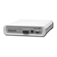
1.5.5 LED Indicators
Power Green On = Power active, Config by DIP switch
Flash = Config by console or SNMP
E1/T1 Mode Stateful Green = E1 mode (75 ohm)
Green/Flash = E1 mode (120 ohm)
Off = T1 mode (100 ohm)
Red/flash = Error in termination setting
Remote Error Stateful Green = remote no error
Red = remote has errors
Off = unknown or no optical link
Optical BER
(Bit Error Rate)
Stateful Green = 0 error rate
Green/flash = 0 to 10
-6
error rate
Red/flash = 10
-6
to 10
-3
error rate
Red = more than 10
-3
error rate
(Optical) Link Stateful Green = Link Good
Red = Link failure
E1/T1 Channel (1~4) Stateful Green = In Service
Off = Out of Service
Red = Loss of Signal
Red/flash = loop back test active
Active (Phone) Stateful Off = On Hook
Green = Off Hook & Connected OK
Green/flash = call out or incoming call (ringing)
Red/flash = Off Hook & connect failed
Red = No Phone Option Installed
SNMP (rear panel) Green Active: ON = SNMP active (flash 1/sec)
Active: OFF = no SNMP option
Link: ON= LAN link OK; OFF = No Link

 Loading...