Appendix A. Miscellaneous
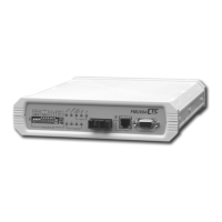
A.3 Console cable pin assignment CAB-DB9DB9F-232-3
1
2
3
4
5
6
7
8
9
1
2
3
4
5
6
7
8
9
1
2
3
4
5
6
7
8
9
DB9F
Terminal
DB9M DB9M
FMUX04
Alarm
NO
Common
NC
100cm 20cm
A.4 Phone pin assignment
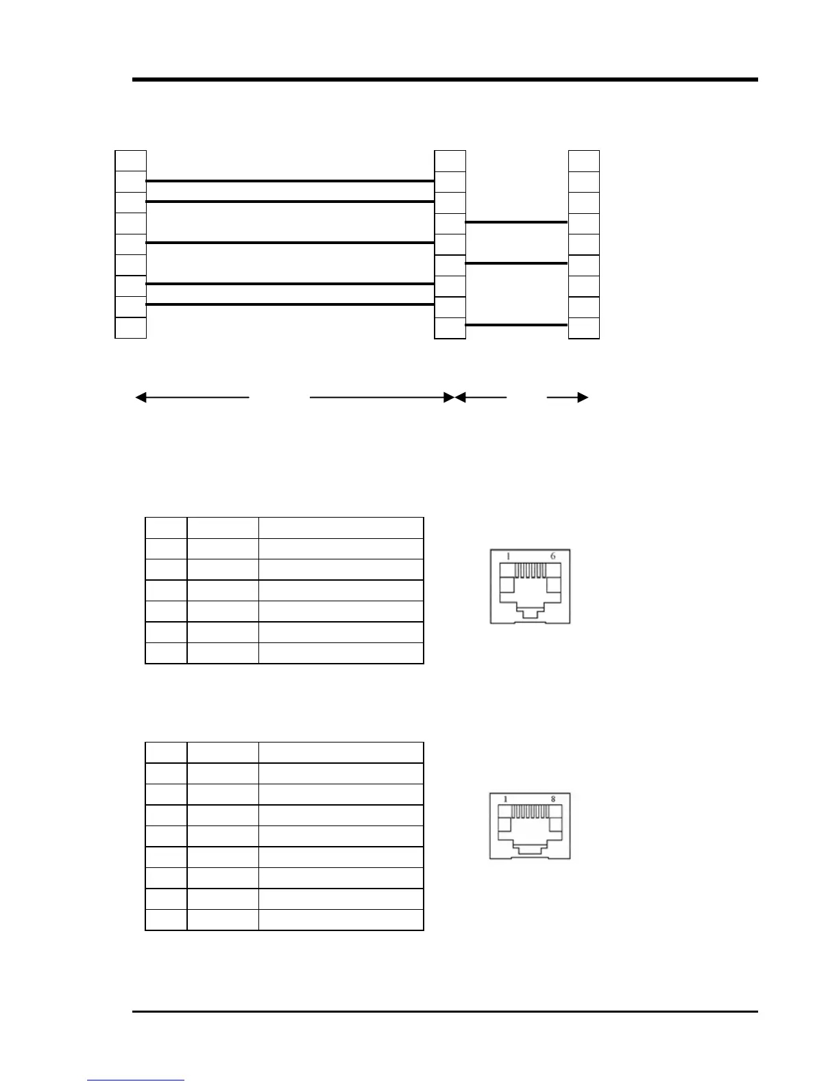
The phone connector is a standard RJ-11 telephone connector located on the front panel of
the FMUX04. The center two pins connect to a standard dial telephone.
Pin Signal Description
1 NC No connection
2 NC No connection
3 Ring Phone connection
4 Tip Phone connection
5 NC No connection
6 NC No connection
A.5 E1/T1 RJ-45 pin assignment
Pin Signal Description
1 RRing Receive (-)
2 RTip Receive (+)
3 NC No connection
4 TRing Transmit (-)
5 TTip Transmit (+)
6 NC No connection
7 Shield Chassis connection
8 Shield Chassis connection
57
 Loading...