Chapter 2. Installation
2.6 Rear Panel Connectors
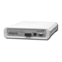
The rear panel of the FMUX04 supports the E1 and T1 interface connection, the AC or DC
power connectors, the power switch and the Ethernet connector for connection to the LAN
network for SNMP control (when the SNMP option is installed). The FMUX04 routes the
signals from the 4 E1/T1 channels to the multiplexing circuitry and sends the multiplexed
signals to the Fiber Interface on the front panel.
Ethernet (SNMP)
Unbalanced E1
Balanced E1/T1
Figure 2-4 : Rear Panel Connections
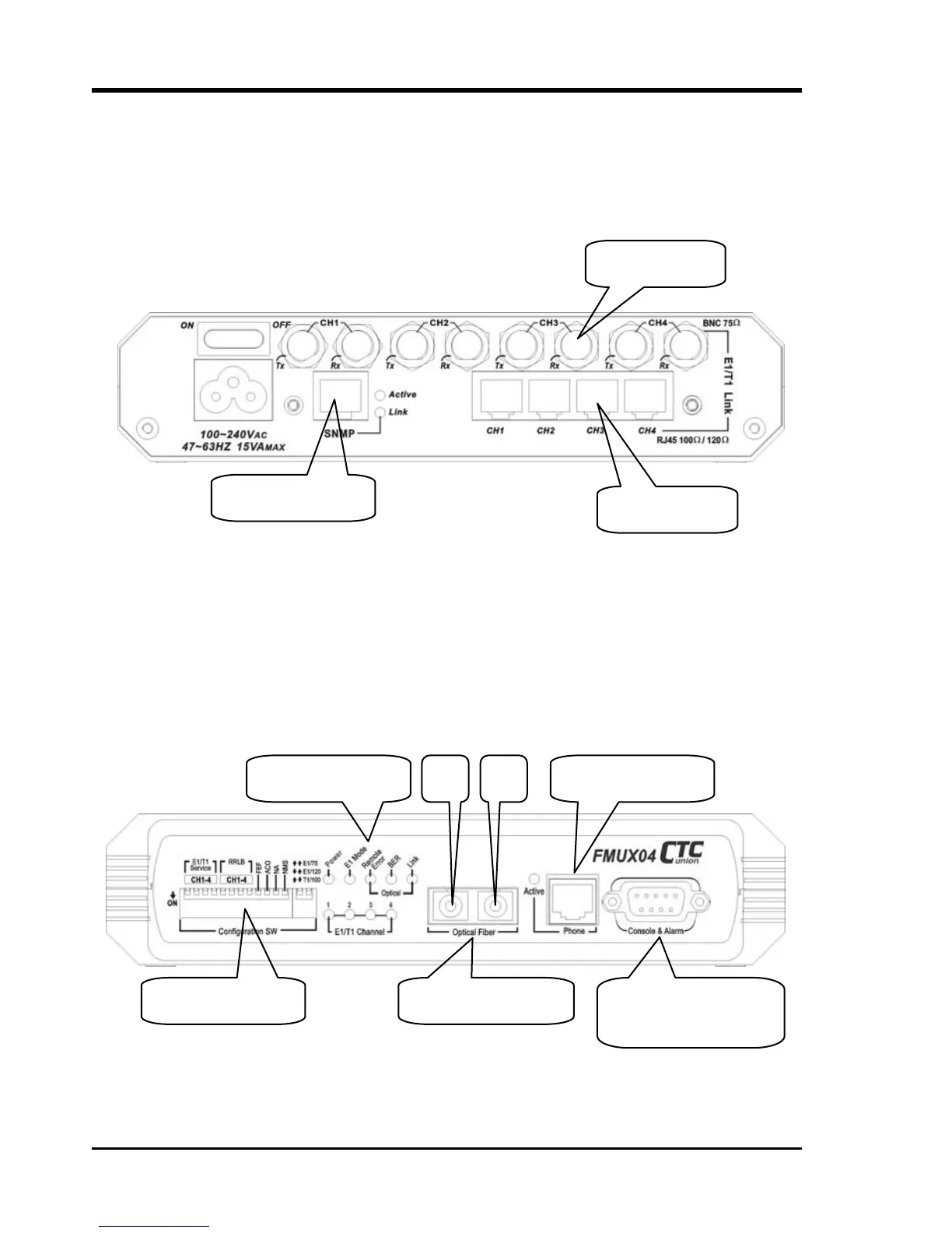
2.7 Front Panel Switches, Connectors and Indicators
The front panel of the FMUX04, holds the optical interface, LED display, DIP switches and
RS-232 Console port/Alarm Relay connector. The optical interface is fixed at the factory per
order. The FMUX04 supports single mode or multimode transceiver with SC, ST, or FC
connector in powers that support 2, 15, 30, 50 or 120KM reach. The front panel also provides
the Order Wire phone jack that can directly connect to any standard telephone set.
DIP switches Optical Transceiver
Order wire phone
Terminal (NMS) and
Alarm Relay contacts
Tx Rx LED Display
Figure 2-5 : Front Panel Controls and Indicators
20
 Loading...