Chapter 2. Installation
2.8.2 SNMP Feature Removal / Replacement
***CAUTION***
This procedure should only be performed by qualified service personnel. In addition, all
power connections must be removed before attempting to open the case.
1. If the unit is installed in a rack, remove all connections and power cord.
2. Loosen the captive thumb screws on the rear of the FMUX04 until the threads are
disengaged from the housing.
3. Gently pull the PCB assembly straight out the rear of the housing. Remove the SNMP
module PCBA from it's protective wrapping. Refer to the graphic on page 10 for the location
of the SNMP option.
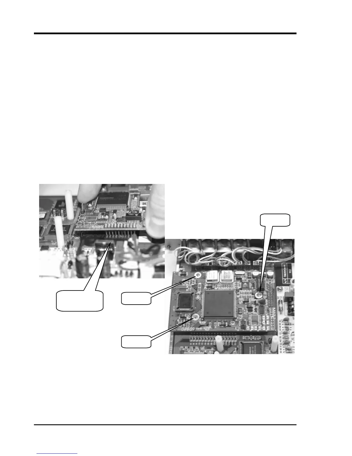
3. Align the connector pins as in the following photos, seat the module, insert the three
securing screws, and tighten lightly.
4. Return the PCBA to the housing and tighten the thumb screws. The unit is now ready to
configuration and use.
Screw
Screw
Align the
Connecto
Screw
Figure 2-9 : SNMP daughter card Removal / Replacement
Note: Follow the instructions in Chapter 4 SNMP to configure the SNMP option.
22
 Loading...