Steering
53
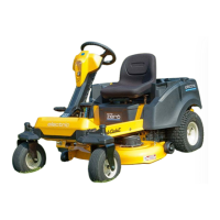
5. Remove the nuts and bolts that hold the sensor to
the sensor bracket using a #2 Phillips screwdriver
and a 1/4” wrench.
See Figure 4.34.
6. Install a new sensor to the sensor bracket using the
nuts and bolts that held the old one in place.
7. Place the two flat washers on the axle casting so
that the holes in the washers line up with the screw
holes.
See Figure 4.35.
8. Install the steering sensor and bracket.
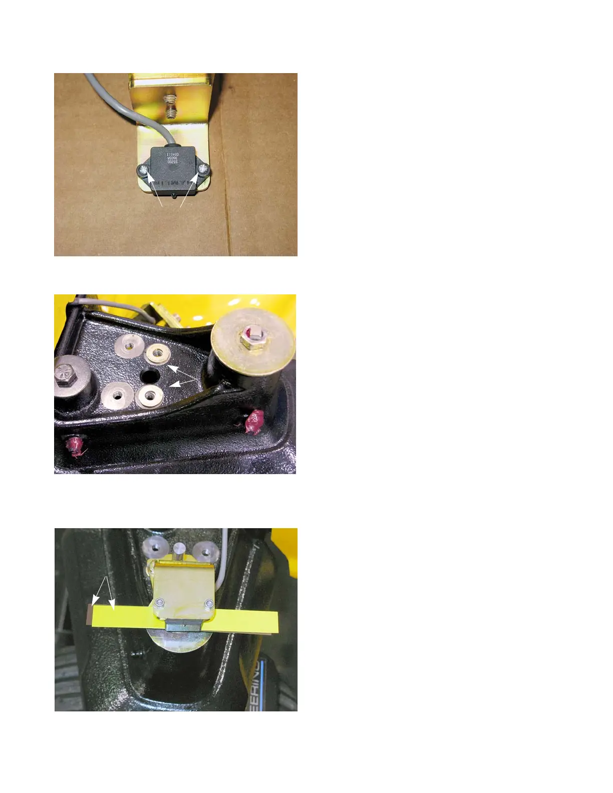
9. Check the steering sensor air gap. Adjust as neces-
sary. See Figure 4.36.
• Slide a non-ferrous feeler gauge between the mag-
net in the head of the screw that holds the yoke in
place and the steering sensor. The steering sensor
air gap should be between 0.025” - 0.035” (0.64 -
0.89 mm). If it is not:
9a. Loosen the two screws that hold the top half of
the steering sensor bracket to the bottom using
a 3/8” wrench.
9b. Slide a 0.030” (0.76 mm) non-ferrous feeler
gauge between the magnet in the head of the
screw that holds the yoke in place and the
steering sensor.
9c. While lightly holding the sensor down on the
feeler gauge, tighten the two screws.
9d. Slide the feeler gauge out from in between the
magnet and the sensor.
NOTE: There should be a slight drag on the feeler gauge
as it is removed. If there is not, readjust the steer
-
ing sensor until there is.
Figure 4.35
Figure 4.36
0.020” + 0.010”
Feeler gauges
Washers
 Loading...