Electrical System
71
Charging circuit
How it works
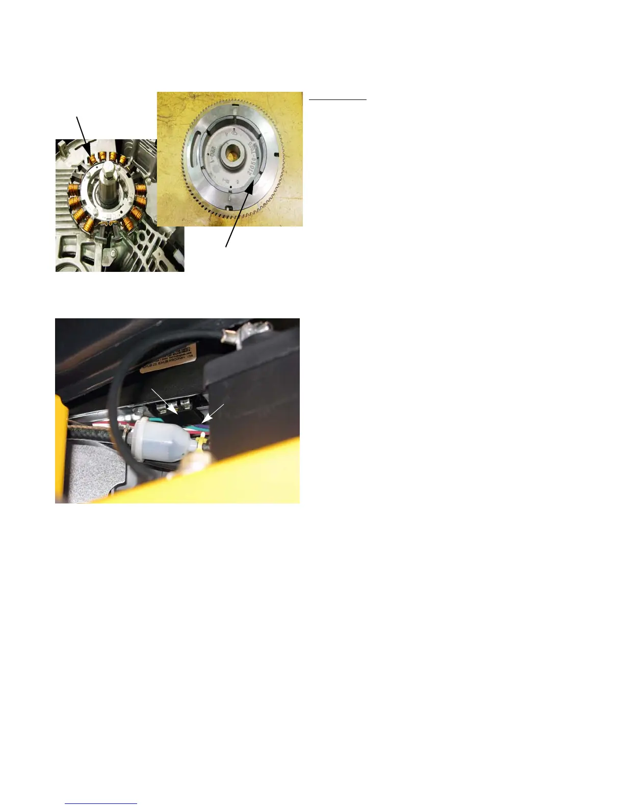
1. When the engine is running, magnets attached to the
underside of the flywheel induce AC (Alternating Cur-
rent) in the stator that is mounted beneath the fly-
wheel. See Figure 7.15.
2. The AC travels from the stator to and from the regula-
tor/rectifier through the two white wires.
NOTE: The magnets inside the flywheel act as a rotor for
the charging system.
3. The regulator/rectifier takes alternating current and
converts (rectifies) it to DC (Direct Current). The reg-
ulator rectifier also regulates the voltage to a nominal
12 volts. See Figure 7.16.
• Actual output is closer to 14 volts, but should be no
more than 15 volts.
• To work properly, the regulator/rectifier must have
a good ground connection to the engine block and
ultimately back to the battery negative post.
4. Regulated DC power leaves the regulator/rectifier.
4a. A purple wire comes out of the regulator/recti-
fier.
4b. The purple wire changes to a red/white trace
wire at the harness connector.
Stator
Rotor
(magnets in recess)
Figure 7.15
Figure 7.16
Regulator/rectifier
Purple wire
www.mymowerparts.com
For Discount Cub Cadet Parts Call 606-678-9623 or 606-561-4983
 Loading...