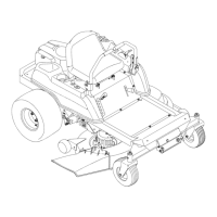
Brakes and Drive System
41
Control pedal shaft assembly
NOTE: The control pedal shaft is an assembly of the brake
pedal shaft and the drive pedal shaft.
To remove/replace the control pedal shaft assembly:
1. Remove the floor board by following the procedures
described in Chapter 3: Body.
2. Install the alignment fixtures and pins by following the
procedures described in Chapter 5: Steering.
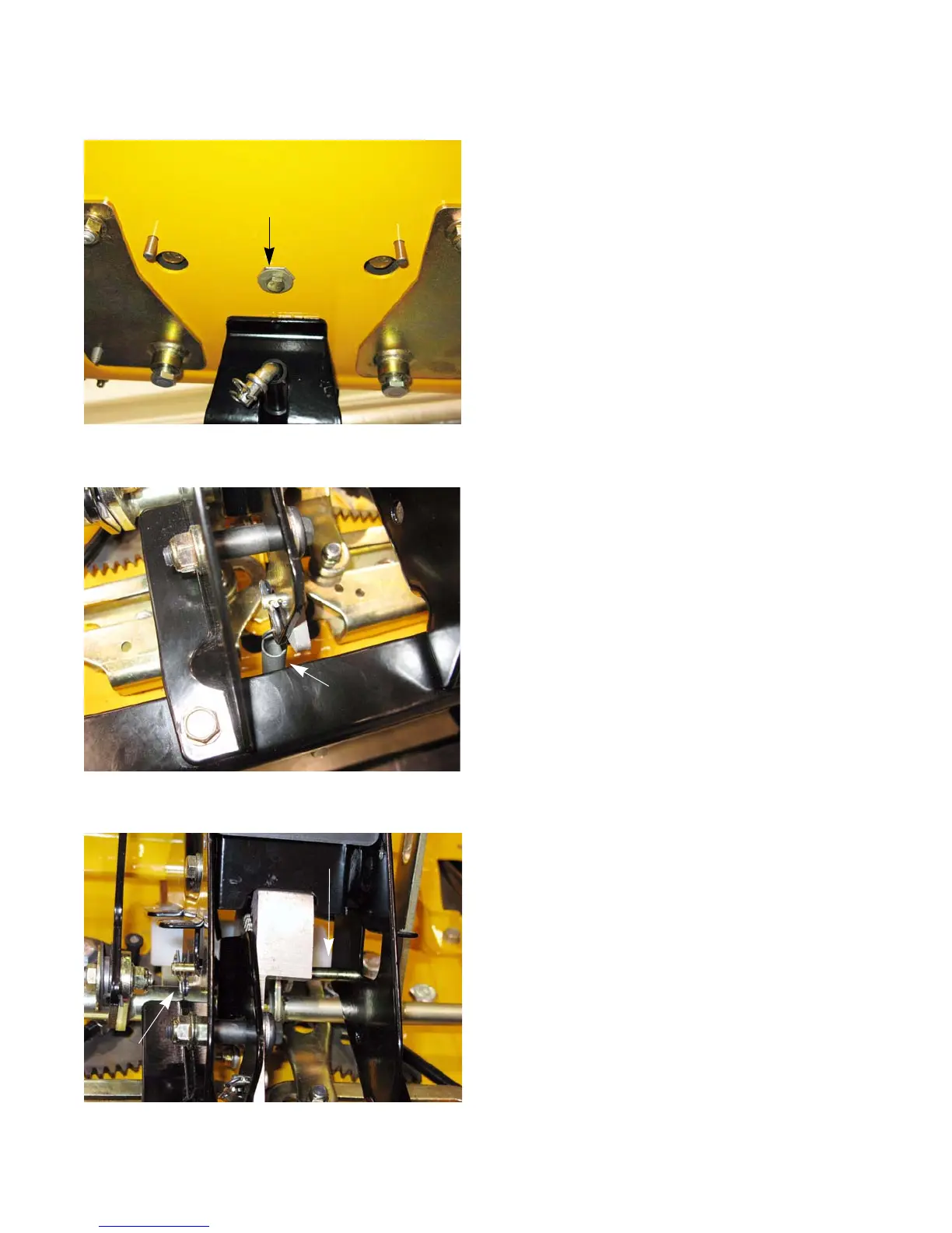
3. Remove the steering shaft bolt from the bottom of the
steering shaft using a 7/16” wrench. See Figure 4.37.
4. Install the screw and washer from the steering wheel
into the top of the steering shaft.
5. Disconnect the parking brake/cruise latch spring.
See Figure 4.38.
6. Remove the bowtie clip from the travel stop pin.
See Figure 4.39.
7. Slide the travel stop pin out of the steering column
assembly.
Figure 4.37
Steering shaft bolt
Figure 4.38
Spring
Figure 4.39
Bowtie clip
Travel stop pin
www.mymowerparts.com
For Discount Cub Cadet Parts Call 606-678-9623 or 606-561-4983
 Loading...