Return to TOC Curtis 1239E-1269E Manual, os 37.0 RevA – May 2021
2 — INSTALLATION AND WIRING
pg. 15
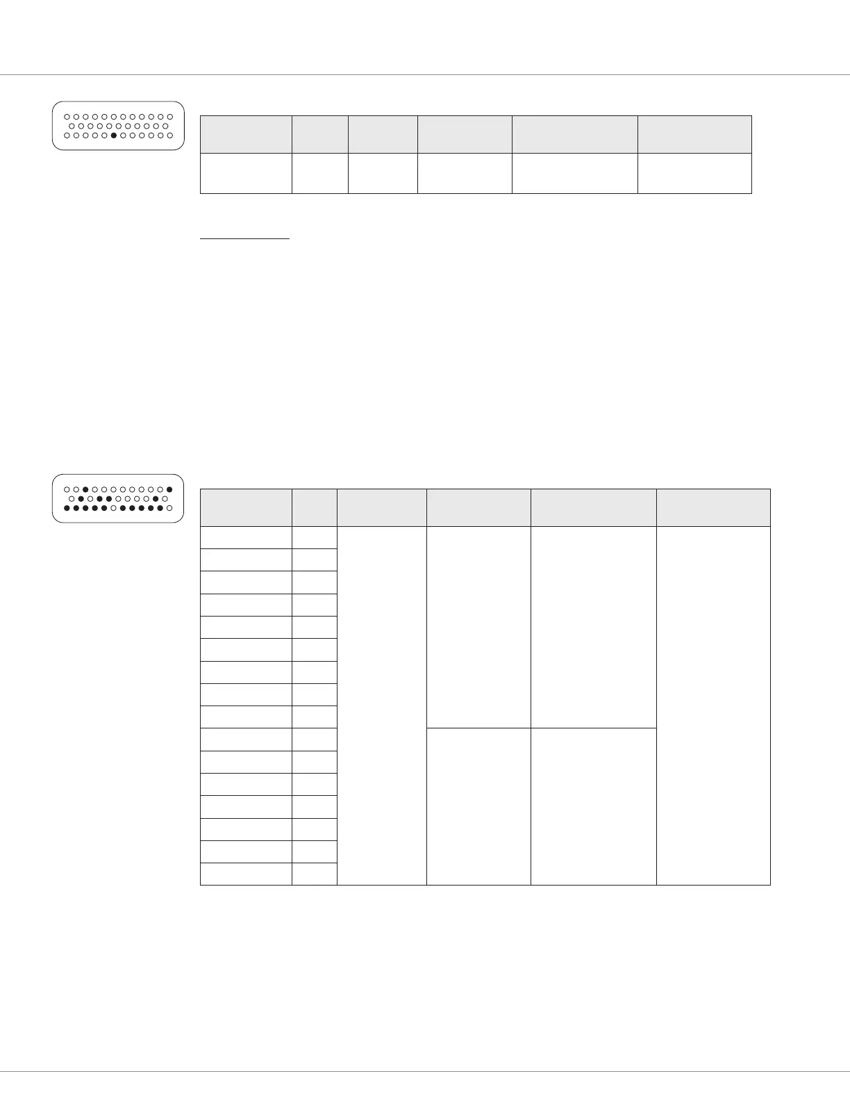
LOW POWER GROUND SPECIFICATIONS
Name Pin
Output
Voltage
Output Current Protected Voltage ESD Tolerance
Low Power
Ground
7 N/A
13A max
continuous
Not Protected
± 8 kV (air
discharge)
13
24
1
23
35
12
Digital Inputs
ese control lines can be used as digital (on/o ) inputs. Normal “on” connection is direct to KSI;
“o ” is direct to low power ground. Input will pull low (o ) if no connection is made. All digital
inputs are protected against shorts to KSI or low power ground.
Nine of these lines (Switches 1–8, 16) are designed to pull current to keep switch contacts clean and
prevent leakage paths from causing false signals.
e remaining lines are digital inputs associated with driver outputs; note that they have much higher
input impedances. e two digital output lines , Digital Out 6 and 7, can also be read as inputs, and
are therefore included in this group.
e digital inputs at pins 24 and 8 can also be used as analog inputs, and are included in that group
as well.
DIGITAL INPUT SPECIFICATIONS
Name Pin
Logic
Thresholds
Input Impedance
to Ground
Protected Voltage ESD Tolerance
Switch 1 24
Rising edge=
4.4V max
Falling edge=
1.5V min
7.0 kΩ
–10V to 20V
± 8 kV
(direct strike)
Switch 2 8
Switch 3 9
Switch 4 10
Switch 5 11
Switch 6 12
Switch 7 22
Switch 8 33
Switch 16 14
Digital Out 6 19
200 kΩ
–5V to 20V
Digital Out 7 20
Driver 1 6
Driver 2 5
Driver 3 4
Driver 4 3
Prop Driver 2
NOTE: The voltage at the switch inputs 3–8 and 16 must be above the high threshold or below the low threshold for proper operation.
Allowing these inputs to fall between these thresholds for more than 100 ms could result in a Supervisor Fault (fault code 77).
13
24
1
23
35
12
Quick Link:
Figures 5 & 6 wiring
diagram p.12-13