Digital Outputs
These signal lines can be used as digital (ON/OFF) or Pulse Width Modulated (PWM) outputs.
Each driver is active low, meaning the output will pull low (to B-) when commanded ON. The
PWM is at a fixed frequency ( 9.7kHz for Outputs 1-4 and 400Hz for Outputs 5-16) but can vary
duty cycle from 0% (off = 0) to 100% (on = 32767). Digital Outputs 1 and 2 are special as these
have current feedback signals (internal) that can be used by VCL to create current sources or
check the output load etc.
If the 1310 Digital outputs are connected to inductive loads, the B+ tab must be connected to the
battery source. This connection provides a path for the internal freewheel diodes to clamp the
turn-off spike. Failure to make this connection with inductive loads can cause permanent
damage to the Curtis 1310 as well as propagate failures of other electronics in the system due to
the high voltage spike caused when an inductive load turns off without a freewheel path.
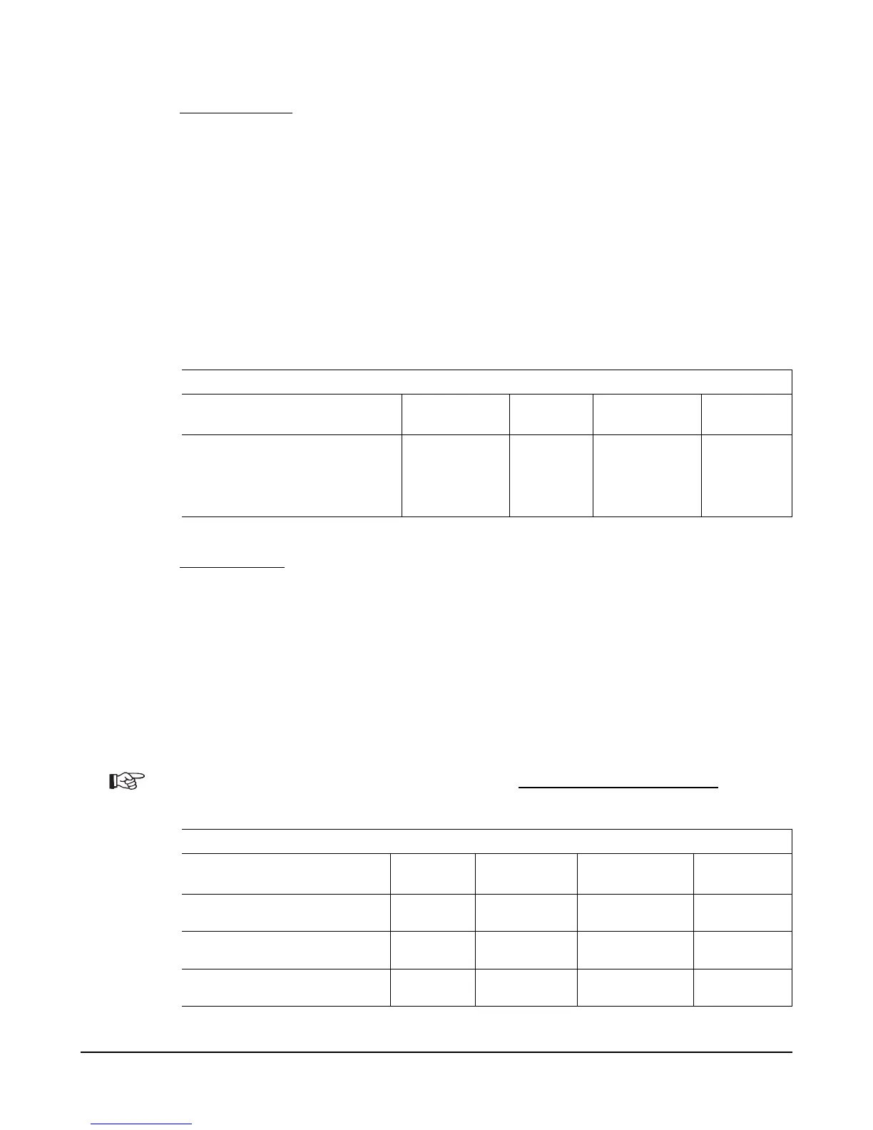
DIGITAL OUTPUT SPECIFICATIONS
SIGNAL NAME PIN
PWM &
Frequency
Output
Current
Protected
Range
ESD
Tolerance
Input/Output 1-16 J1-1 thru 22
0-100% at
Outputs 1-4
~9.7Khz
Outputs 5-16
~400 Hz
Sink 3amps 24-48V models:
-0.5 to 64v
48-96V models:
-0.5 to 124v
± 8 kV
(air discharge)
Analog Inputs
The 1310 provide four analog inputs. These inputs can easily be configured for use with
potentiometers. VCL allows each input to be independently set up as a voltage input or as a 2-
wire or 3-wire resistance input. Voltage inputs can be connected directly to the Wiper input
(with B_ or GND for the return line). Rheostats (2-wire) are connected between the Pot Wiper
and Pot Low and a 3-wire potentiometer has the resistance element connected between the Pot
High and Pot Low signals and the wiper connected to the Wiper signal. The corresponding
VCL setup must be used to allow the 1310 to properly detect and scale the signal.
Although designed to be used with potentiometers, Pot High and Pot Low signals are monitored
by analog pins in the 1310 and thus have a limited use as analog inputs. Note that these pins
have a low input impedance (~680Ω) which could be damaged by moderate voltages from a low
impedance source.
ANALOG INPUT SPECIFICATIONS
SIGNAL NAME PIN
Operating
Voltage
Input
Impedance
Protected
Voltage
ESD
Tolerance
Wiper 1-4 J4-6 thru 9 0 - 5v
5kΩ -1v to 30v ± 8 kV
(air discharge)
Pot High J4-5 0 - 5v
680Ω to +5V -1v to 12v ± 8 kV
(air discharge)
Pot Low J4-10 0 - 5v
680Ω to ground -1v to 8v ± 8 kV
(air discharge)
1310 Vehicle Control System Users Manual Release Rev B Page 17 of 51