4- INTERNAL DATA
INTERNAL DATA
MONITOR MENU
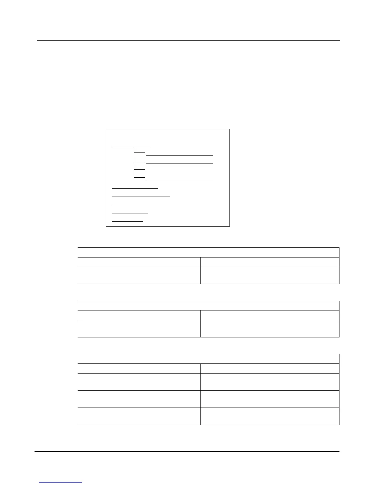
The 1311 Handheld or 1314 PC programmer provides access to many interal variables that are
continuously read and updated. The values are displayed under the MONITOR menu. The
variables are further organized into submenus as depicted below;
CAN STATUS
PDO1 MISO BYTE MAP
PDO1 MOSI BYTE MAP
PDO1 MISO BYTE MAP
PDO1 MOSI BYTE MAP
PWM OUTPUTS
ANALOG OUTPUTS
ANALOG INPUTS
POT INPUTS
SWITCHES
PWM OUTPUTS SUB MENU
DISPLAY VARIABLE RANGE DESCRIPTION
Channel #
PWM#_Output
0–32767
0–32767
PWM output value (32767 = 100%) of one of the 16 PWM
signals. Where # = 1 through 16
ANALOG OUTPUTS SUB MENU
DISPLAY VARIABLE RANGE DESCRIPTION
Channel #
DAC#_Output
0–32767
0–32767
Analog output value (32767 = 10v) of one of the 2 DAC
channels. Where # = 1 or 2
ANALOG INPUTS SUB MENU
DISPLAY VARIABLE RANGE DESCRIPTION
KSI Filtered
KSI Filterd
0–100.0 v
0–10000
Filtered and calibrated value of the B+ / KSI input signals.
1 volt = 100 counts
KSI Raw
KSI_Raw
0–1023
0–1023
Unfiltered (raw) value of the B+ / KSI input signals
~ 1 volt = 9.5 counts (uncalibrated)
Channel #
ADC#_Input
0–1023
0–1023
Analog input value (~1023 = 5v) of one of the 16 ADC
channels. Where # = 1 through 16
1310 Vehicle Control System Users Manual Release Rev B Page 22 of 51
4
Second Level
Submenu
⇓