Curtis 1207B Manual
11
2 9 J U N E 2 0 1 2 D R A F T
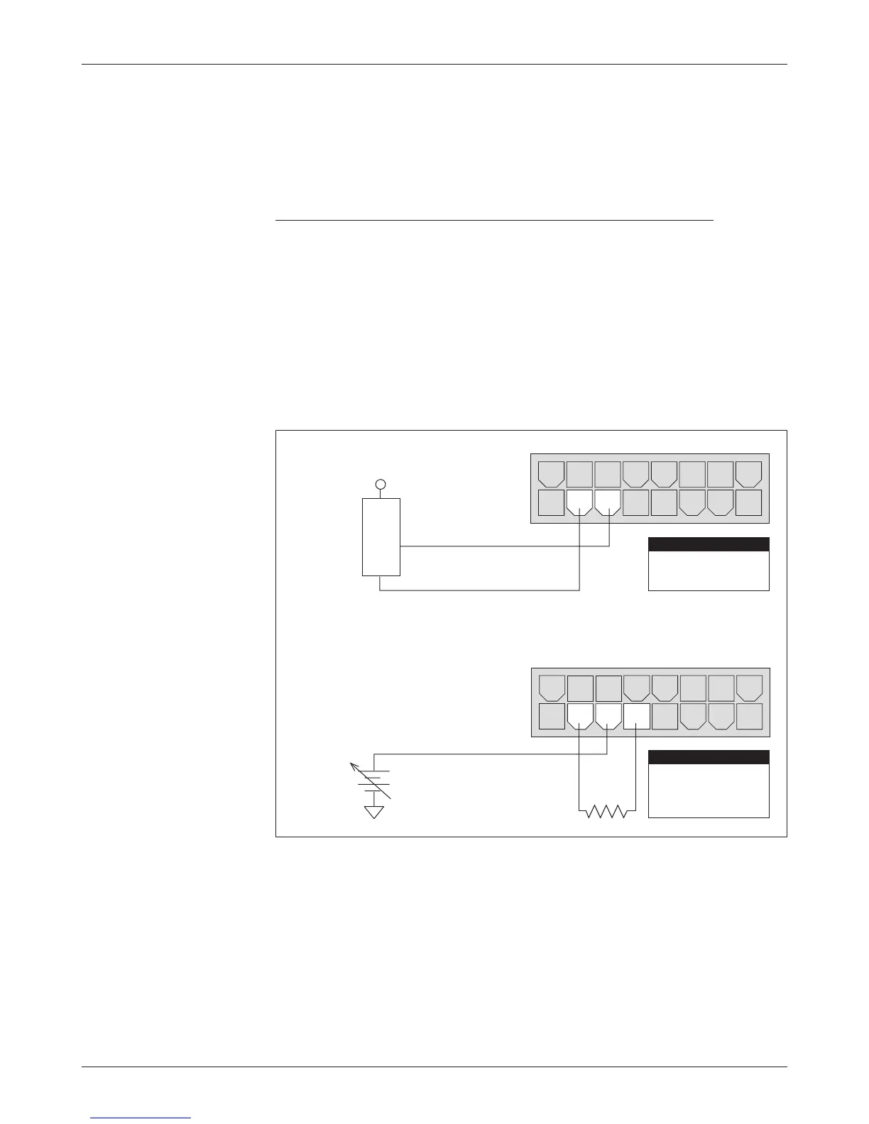
(b) Ground-referenced
0–5V throttle
(a) 0–5V throttle sensor
Fig. 7 Wiring for 0–5V
throttle (“Type 2”).
throttle mechanism must provide signals to the controller’s forward and reverse
inputs independent of the throttle pot resistance. The controller will not sense
direction from the pot resistance.
0–5V, 3-Wire Potentiometer, and Electronic Throttles (“Type 2”)
With these throttles (“Type 2” in the programming menu), the controller looks
for a voltage signal at the pot wiper/0–5V input of the controller (Pin 6). Zero
speed corresponds to 0V and full speed corresponds to 5V. Pot Low is the cur
-
rent return path for all Type 2 throttles.
0–5V Throttle
Two ways of wiring the 0–5V throttle are shown in Figure 7. If a throttle sen-
sor is used, the sensor’s ground return current must be less than 10 mA. If the
0–5V throttle input (Pin 6) exceeds 8 volts, the controller will shut down.
2 — INSTALLATION & WIRING
8 7 6 5 4 3 2 1
8 7 6 5 4 3 2 1
16 15 14 13 12 11 10 9
+
-
+
B-
16 15 14 13 12 11 10 9
4.7 kΩ
(Shunt impedance 150 k
Ω
to ground)
Pin 7
Pin 6
Pin 5
Pot Low
0–5V Input
Pot High
PIN KEY
Pin 7
Pin 6
Pot Low
0–5V Input
PIN KEY
SENSOR GROUND
SENSOR OUTPU
T
0–5V
SENSOR