6
Curtis 1207B Manual
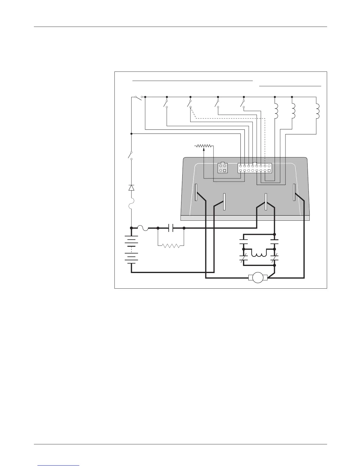
WIRING: Standard Configuration (Series Motor)
The basic wiring for series motors with field reversing is shown in Figure 3.
Fig. 3 Standard
wiring diagram
(series motor),
Curtis 1207B controller.
The configuration shown in Figure 3 is a typical arrangement for a series mo-
tor. Curtis controllers are designed for use in a wide range of applications, and
accordingly can be installed in a variety of ways to best meet customer needs.
Note: The emergency reverse check feature (wiring shown by dashed line) is
a factory option.
2 — INSTALLATION & WIRING
MULTI
MOD
E
EMERGENCY
REVERSE
A2
A1
REVERSE
CONT
ACTOR
PRECHARGE RESISTOR
(250
Ω, 5 W)
BRAKE
FORWARD
CONTACTORS
MAINREVERSE
SWITCHES
CONTROL
FUSE
M- A2
B+B-
FORWARD
CONTACTOR
POWER
FUSE
KEYSWITCH
POLARITY
PROTECTION
DIODE
S1
S2
MAIN
CONTACTOR
B-
B+
FORWARD
REVERSE
THROTTLE
5kΩ–0 (TYPICAL)
A