Curtis 1207B Manual
7
2 9 J U N E 2 0 1 2 D R A F T
Power Wiring for Series Motor
In every wiring configuration, it is imperative that the field be wired between
the controller’s
B+ and A2 terminals and that the armature be wired between
the M- and A2 terminals. The internal plug diode used in the 1207B is con-
nected between
M- and A2. Therefore, the armature and field positions cannot
be interchanged. Reversing contactors can be used to switch either the armature
or the field.
Control Wiring for Series Motor
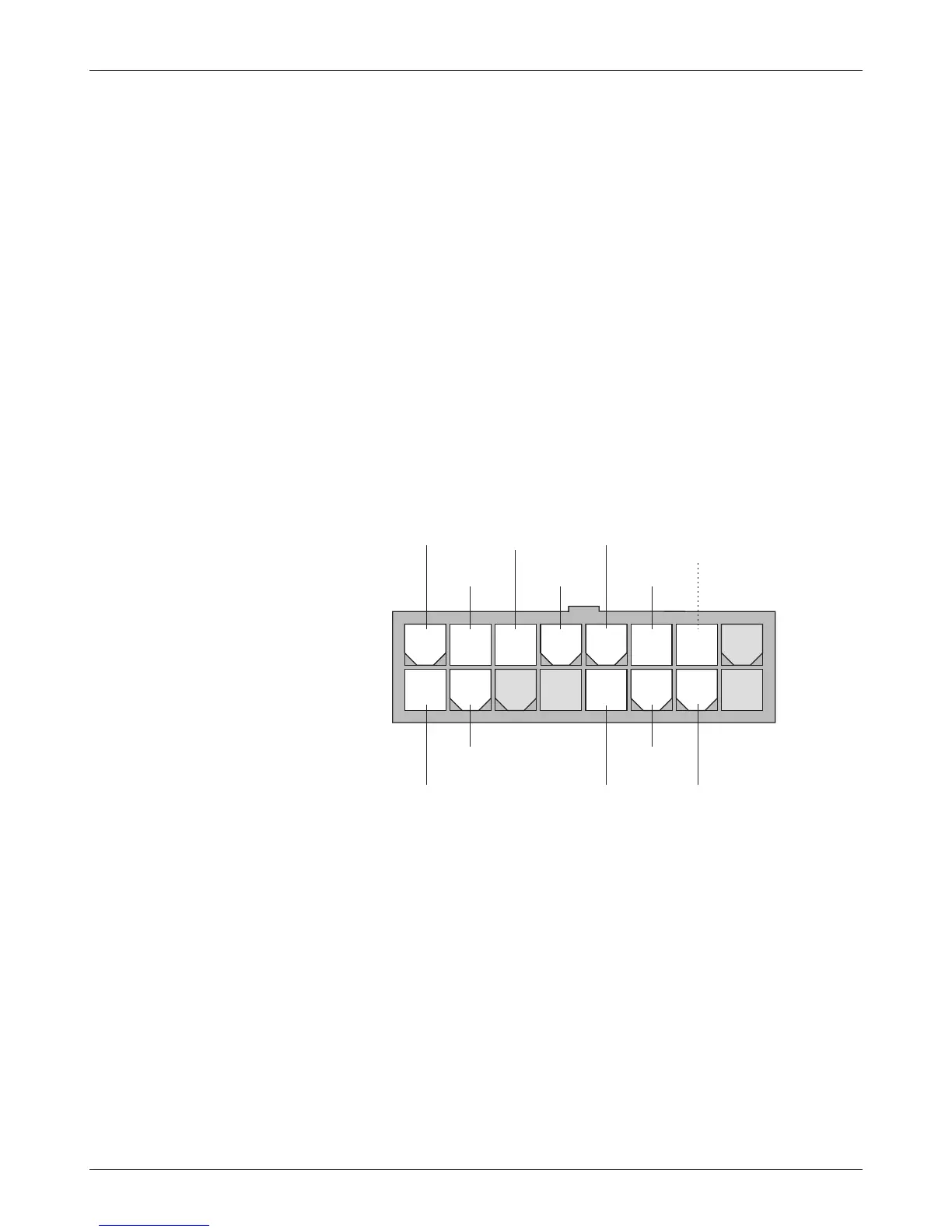
Wiring for the input switches and contactors is shown in Figure 3 (see detail
below). The main contactor, if one is used, is normally connected directly to
the controller. Optionally, the main contactor can be switched directly by the
keyswitch or brake, leaving Pin 4 unconnected.
The throttle shown in Figure 3 is a 5k
Ω–0 type. Various other throttles can
also be accommodated, and are discussed in the throttle wiring section.
2 — INSTALLATION & WIRING
16-pin detail (see Fig. 3):
BRAKE
MULTI
MODE
EMERGENCY
REVERSE
FORWARD
REVERSE
KEYSWITCH
EMERGENCY
REVERSE
CHECK
OUTPUT
MAIN
CONTACTOR
FORWARD
CONTACTOR
REVERSE
CONTACTOR
2-WIRE POT
(5 kΩ)
POT
LOW
8 7 6 5 4 3 2 1
16 15 14 13 12 11 10
9
16-pin detail (see Fig. 3):