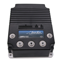
Curtis 1207B Manual
5
2 9 J U N E 2 0 1 2 D R A F T
CONNECTIONS: High Current
Four tin-plated copper bus bars are provided for the high current connections
to the battery and motor:
M- output to motor armature
B- negative connection to battery
B+ positive connection to battery/field
A2 plug diode to motor armature
Cables are fastened to the bus bars by M8 (
5
⁄
16
") bolts.
When tightening the bolts, two opposing wrenches should
be used to prevent bending the bus bars and putting undue
strain on the internal connections.
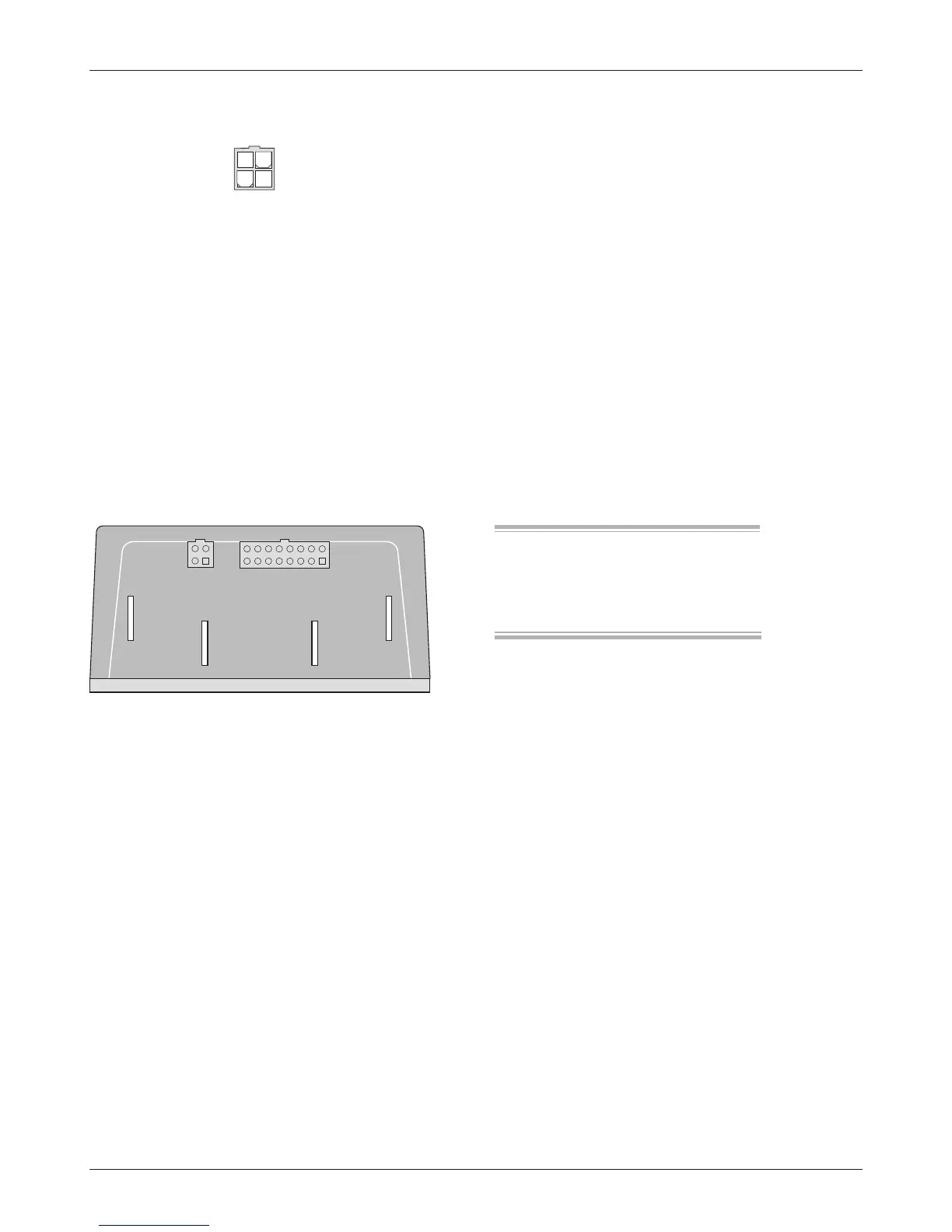
Programmer Connector
A 4-pin Molex connector is provided for the 1311 handheld programmer or
the 1314 PC Programming Station. A mating cable is supplied with the 1311
handheld programmer.
Status LED
The Status LED, located on top of the controller, displays flashing codes to
indicate controller status; the codes are listed in Section 5.
2 — INSTALLATION & WIRING