Curtis 1207B Manual
13
2 9 J U N E 2 0 1 2 D R A F T
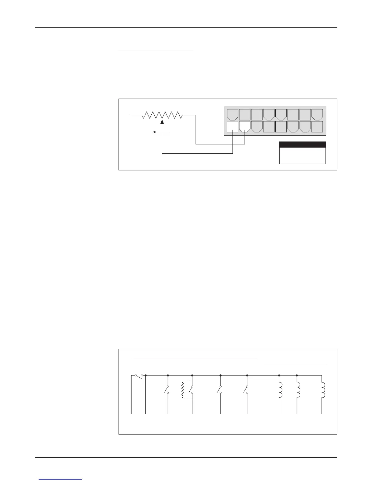
0–5kΩ Throttle (“Type 3”)
The 0–5kΩ throttle (“Type 3” in the programming menu) is a 2-wire resistive
throttle that connects between the 5k
Ω–0/0–5kΩ pin (Pin 8) and the Pot Low
pin (Pin 7), as shown in Figure 10. It doesn’t matter which wire goes on which
pin. Zero speed corresponds to 0
Ω and full speed corresponds to 5kΩ.
Fig. 11 Alternative
wiring for 1207B
emergency reverse check.
Fig. 10 Wiring for
0–5
Ω
throttle (“Type 3”).
WIRING: Emergency Reverse Check
An optional wire connected directly to the emergency reverse (belly button)
switch provides for broken wire detection when that option is enabled at the
factory. The emergency reverse check output wire provides a dc bias to the
emergency reverse circuit to check for continuity. If there is no continuity in
the circuit, the controller shuts down and a fault code is indicated.
This feature must be enabled at Curtis. If the option is selected and the
check wire is not connected, the vehicle will not operate. If the option is not
selected and the check wire is connected, no harm will occur—but continuity
will not be checked.
The emergency reverse check output wire is connected to Pin 10, as shown
by the dashed lines in the two basic wiring diagrams (Figures 3 and 4).
Alternatively, a 9.1 k
Ω resistor can be wired directly across the emer-
gency reverse switch to provide the dc bias, as shown by the dashed line in
Figure 11.
2 — INSTALLATION & WIRING
8 7 6 5 4 3 2 1
FASTER
16 15 14 13 12 11 10 9
5kΩ POT
Pin 8
Pin 7
5kΩ–0
Pot Low
PIN KEY
MULTI
MOD
E
EMERGENCY
REVERSE
For rest of wiring diagram, see Fig. 3 (series motors) or Fig. 4 (compound motors).
BRAKE
FORWARD
CONT
ACTORS
MAIN
REVERSE
SWITCHES
FORWARD
REVERSE
9.1 kΩ