8
Curtis 1207B Manual
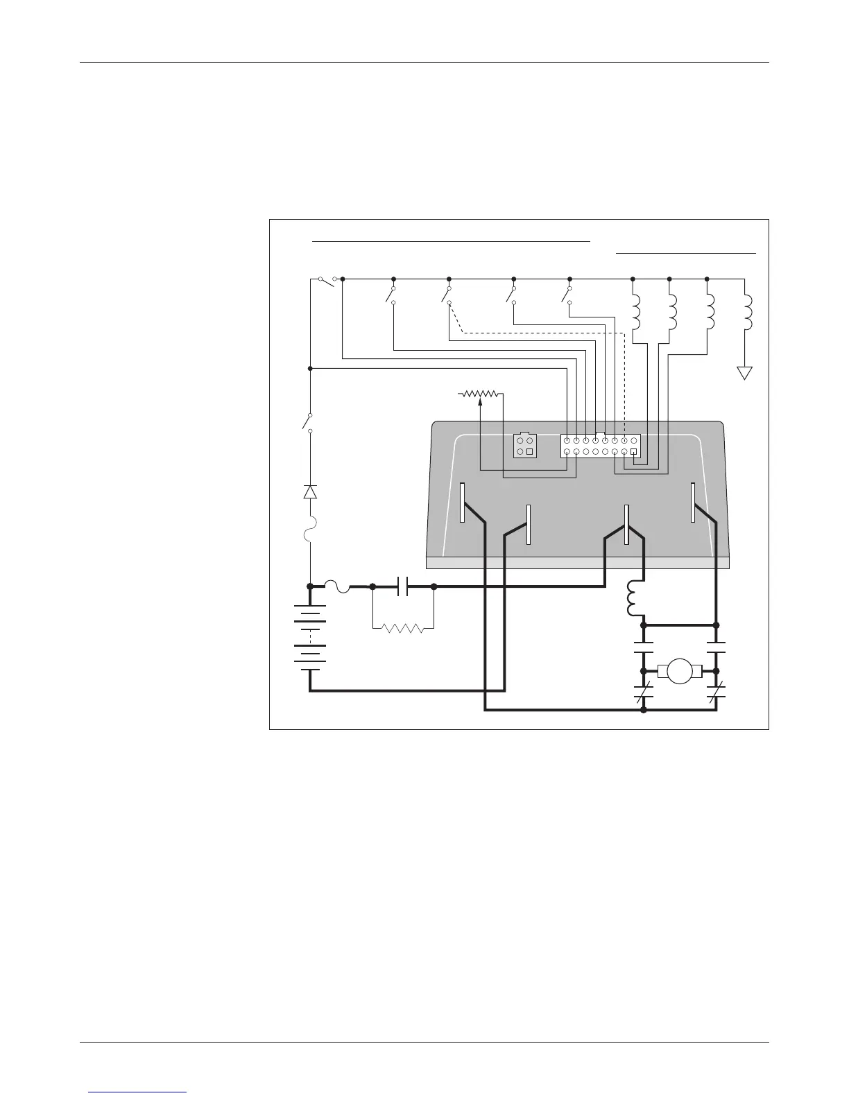
WIRING: Compound Motor Configuration
A specially configured controller is available for compound motor applications.
In this controller, the MOSFET output driver is used to drive the shunt field.
The wiring for a compound wound motor with armature reversing is shown
in Figure 4.
Fig. 4 Compound
motor wiring diagram,
Curtis 1207B controller.
The configuration shown in Figure 4 requires the use of a compound wound
motor. Pure shunt motors cannot be used with 1207B controllers. Although
the configuration shown is typical, various other configurations are possible.
Note: The emergency reverse check feature (wiring shown by dashed line) is
a factory option.
2 — INSTALLATION & WIRING
MULTI
MODE
EMERGENCY
REVERSE
A2
A1
REVERSE
CONTACTOR
PRECHARGE RESISTOR
(250
Ω, 5 W)
BRAKE
FWD
CONTACTORS
MAINREV
SWITCHES
CONTROL
FUSE
M-
A2
B+B-
FORWARD
CONTACTOR
POWER
FUSE
KEYSWITCH
POLARITY
PROTECTION
DIODE
S1
S2
MAIN
CONTACTOR
B-
B+
FORWARD
REVERSE
SHUNT
THROTTLE
5kΩ–0 (TYPICAL)
A
B-