Curtiss-Wright | Tritex II AC 90, 115 Rev. X PN39892 7/12/22
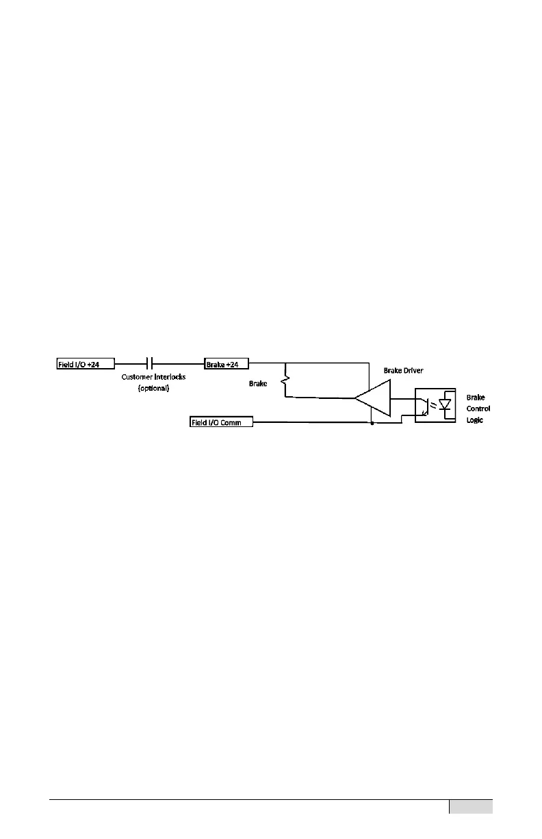
If customer supplied interlocks remove power to the Brake +24V
terminal, the brake will engage even while the drive is enabled and
commanding motion. The interlocks should also disable (not just stop)
the drive to prevent the drive from pushing against the brake.
The negative side of the brake is connected to Field I/O common. The
Brake +24V can be connected directly to Field I/O +24V. A jumper is pre-
wired on units with connectors for this purpose. Power may be applied to
the Brake +24V terminal from a separate supply or through customer
interlocks.
Internal brake control logic operates as follows: Starting from the
disabled state with brake engaged, when the drive enables the brake
releases after a release delay to allow time for the motor current to
become active and hold the load. Starting from the enabled state with the
brake released, when the drive is disabled the drive will immediately
apply full current toward zero velocity, bringing the motor to a an abrupt
stop and engage the brake, then after an engage delay the drive will be
disabled. See the I-O Assignment section of the Software Manual for
more information on brake related status and command signals.
Brake Connections
Analog Input
An analog input is provided for use as a position, velocity or current
command. The input can be configured to operate using a 0-10 Vdc
signal, or using a +/- 10 Vdc signal. (See Software Manual for
configuration and scaling of the analog input)
 Loading...