Curtiss-Wright | Tritex II AC 90, 115 Rev. X PN39892 7/12/22
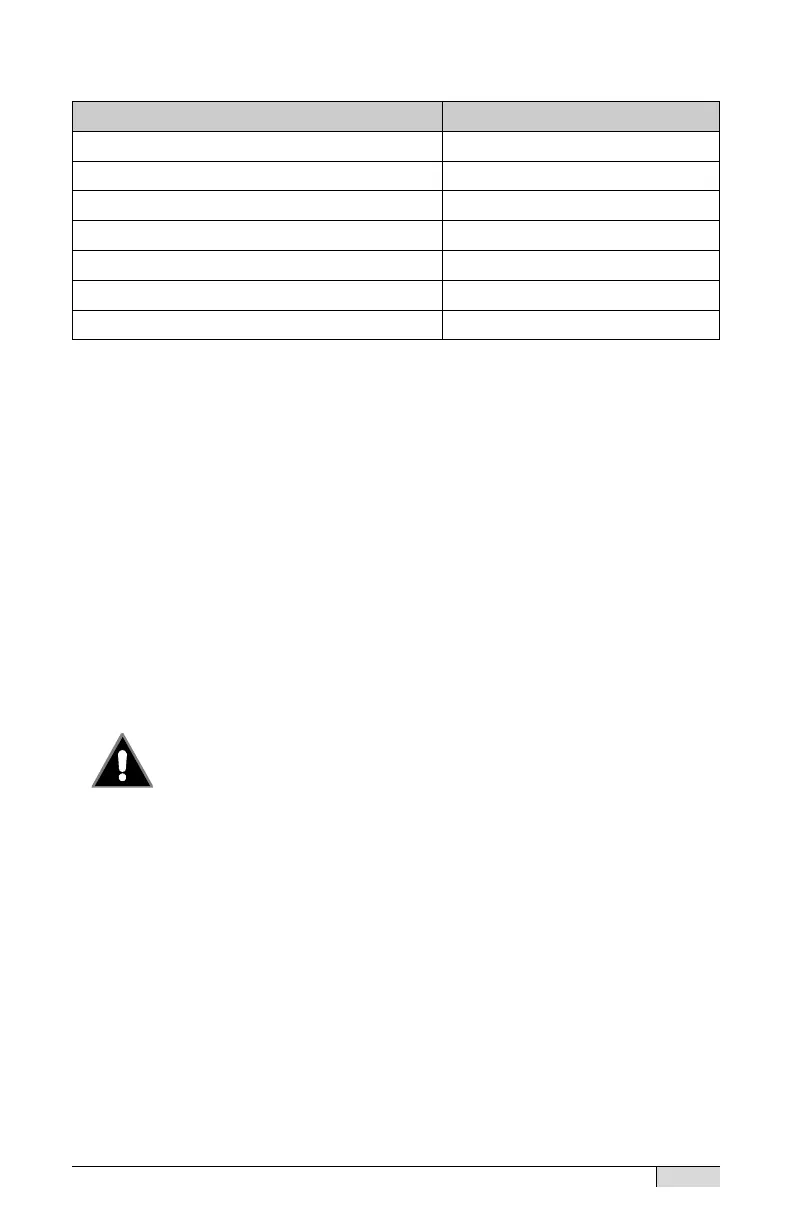
Digital Output Specifications
On state maximum continuous current
On state voltage drop (@ 100 mA)
Inductive Energy Handling
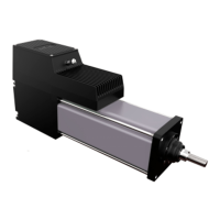
Actuator Brake Option
The actuators may be ordered with a holding brake option. This brake
is a “Parking Brake” and will wear out rapidly if used as a “Stopping
Brake”, It should only be allowed to apply during motion when other
control is not possible, such as a drive fault condition. The brake
engages when power is removed from the brake. The Tritex II has
internal brake control logic so the recommended installation is to simply
connect a constant 24 Vdc +/- 10% power source for the brake circuit.
Typically a single supply is used for brake power and I/O power. Note
that the voltage tolerance for the brake is tighter than for I/O power. If a
separate supply is used, it must have overcurrent protection with the
same ratings as with the I/O supply.
Do not apply or drag the brake when motor / actuator
is moving.
System design must avoid routine application of the brake
when in motion. Only limited motion under infrequent conditions is
acceptable. Brake control voltage lower or higher than 24V +/- 10% may
cause the brake to drag which causes wear and heat.
It is not possible to apply power directly to the brake to disengage it. If
the brake is to be released when main power is removed, control logic
power must be applied and the brake override function must be used.
Brake, I/O and Control Logic power may all use a single power supply. If
the actuator has a Manual Drive option, it is acceptable and may be
necessary to move the actuator manually without releasing the brake.
 Loading...