Cybex Sport+ Treadmill Owner’s and Service Manual
Service
Page 7-37
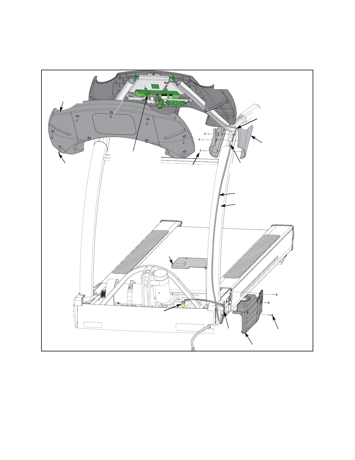
E. Route the cable into the access hole.
F. Connect the display cable to the lower control board at P1 and P2.
7. Secure the cable.
A. Using a Phillips head screwdriver, open the clip described in step 5D and secure the
cable in the clip.
B. Locate the line on the display cable described in step 6D and tie the cable with the
wire tie near the bottom of the upright.
C. Open the wire holder at the junction, put the cable inside and close the wire holder.
Figure 33
Shield
Display Cable
Screws (4)
Screws (9)
Screws (3)
Left
Junction
Covers
P3 and P8
Connectors on
Upper Display
Board
Console
Back Cover
P1 and P2 on
Lower Board
Left Side Cover
NOTE: “Right” and “left” denote
user orientation.
Access
Hole
Bottom
Hole
Wire
Holder
Upright