Assembly and Set Up
Page 2-9
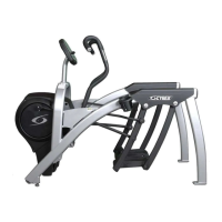
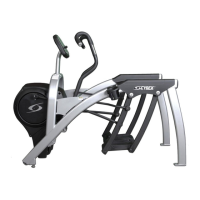
Cybex Arc Trainer 750A/750AT Owner’s Manual
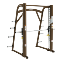
9. Attach 750A cables.
Locate the upper display cable and plug into the lower display cable. See Figure 5.A.
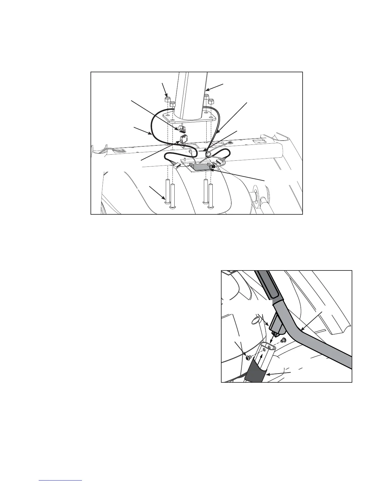
Figure 6 (750A)
Locate the contact heart rate cable and plug into heart rate board. See Figure 5. B.
Plug the heart rate disply cable (threaded through console mount in step 8C) into the heart rate board. C.
NOTE: Ensure cable connectors are securely fastened. Tighten cable strap. See Figure 5.
Figure 5 (750A)
Heart Rate
Display Cable
Upper Display
Cable
Lower Display
Cable
Cable Strap
Contact Heart
Rate Cable
Heart Rate
Board
#12
#13
#2a
10. Attach 750A console and handrail assembly.
Locate four nylon locknuts (#12) and four BHSCS A.
.375-16 x 2.25 (#13). See Figure 5.
With an assistant, place the console assembly (#2a) and B.
handrail assembly (#2b) in the correct position on the
main frame.
NOTE: Confi rm that no cables are pinched while lowering the
console.
Insert (from underneath) the four C. BHSCS .375-16 x 2.25
(#13). Hand thread the four .375-16 nylon locknuts (#12)
in position. See Figure 5. Do not tighten at this point.
Apply loctite (#16)D.
to and insert the four BHSCS .375-16
x .50 SS (#14d) as shown in Figure 6. Do not tighten at
this point.
#14d
#2b
Hold the four BHSCS .375-16 x 2.25 (#13) with a 7/32” Allen wrench (#15) while tightening with a E.
9/16” open end wrench to secure console.
Using a 7/32” Allen wrench, tighten the four BHCS (#14d) to secure the handle assembly. See F.
Figure 6.
Pull rubber sleeves up to cover handle-to-frame connections. G.
(both sides)
rubber sleeve
handle-to-frame
connection

 Loading...