Assembly and Set Up
Page 2-10
Cybex Arc Trainer 750A/750AT Owner’s Manual
NOTE: For 750A assembly, skip to step 12.
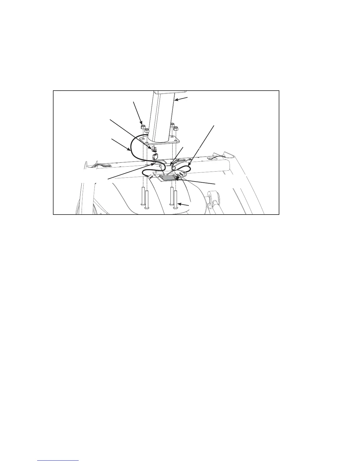
11. Attach 750AT console assembly.
Locate the console assembly (#2a), four .375-16 nylon locknuts (#12) and four A. BHSCS
.375-16 x 2.25 (#13).
Locate the upper display cable and plug into the lower display cable. See Figure 7B.
Locate the heart rate display cable and plug into heart rate board. See Figure 7. C.
Locate the contact heart rate cable and plug into the heart rate board. Tighten cable strap.D.
Insert (from underneath) the four E. BHSCS .375-16 x 2.25 (#13). Hand thread the four .375-16 nylon
locknuts (#12) in position. See Figure 7.
NOTE: Confi rm that no cables are pinched while lowering the console.
Hold the four BHSCS .375-16 x 2.25 (#13) with a 7/32” Allen wrench (#15) while tightening with a F.
9/16” open-end wrench to secure console. See Figure 7.
Figure 7 (750AT)
Heart Rate
Display Cable
Upper Display
Cable
Contact Heart
Rate Cable
Lower Display
Cable
#2a
#13
#12
Cable
Strap
Heart Rate
Board

 Loading...