Cybex Pro+ Treadmill Owner’s & Service Manual
Service
Page 7-20
C. Using a straight-edge (such as the lower
board shield), line up the face of the
flywheel pulley with the face of the front
roller pulley until they are flush. See
Figure 10. NOTE: Do not put the drive
belt on until step 18A.
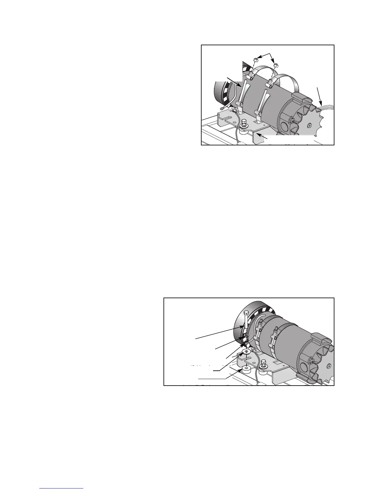
17. Secure the motor straps.
NOTE: Tighten motor strap to 80 in-lbs.
A. Loop each strap through the motor
saddle and position each screw vertically
as shown in Figure 16. NOTE: The motor
strap will be creased slightly where it
pressed against the motor saddle, be sure
the strap is in its original position.
B. Close each motor strap and use a 7/16” wrench with a deep socket to tighten each
nut securely (80 in-lbs). See Figure 16.
18. Align the drive belt.
A. Place the drive belt over the flywheel pulley and confirm that the drive belt is
positioned three grooves over from the face of the flywheel and three grooves over
from the face of the pulley. See Figure 10.
19. Connect the motor cables.
A. Connect the motor cable to the lower board and line filter as shown in Figure 13 (red
to A1, black to A2, yellow to BW and green to the line filter). NOTE: For internationally
installed treadmills only, the green cable goes on the ground stud tab.
B. Place the flat washer on the
motor saddle followed by the
ground terminal, split washer
and screw. See Figure 17.
NOTE: Be sure that the
spacers are still in place
below the saddle.
C. Using a 1/2” socket wrench,
tighten both screws on the
motor saddle.
D. Using wire ties, tie the motor
cable to the base so that no
wires get pinched. See Figure 18. NOTE: Be sure that the wires are tied away from the
fan and running belt. For internationally installed treadmills only, place the ferrite
(shown in Figure 18) removed in between the wire ties.
Figure 17
Ground Terminal (1)
NOTE: The ground
terminal must go
between the two
washers.
Flat Washer (2)
Split Washer (2)
Screw (2)
Spacer (2)
Figure 16
Motor Strap
Screws
(Position
Vertically)
Motor Saddle
Nuts
Motor Exit
Wire
(Position at
3 O’clock)