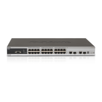
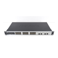
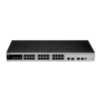
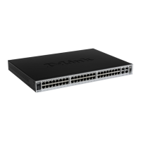
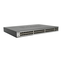
DES-3526 / DES-3526DC Fast Ethernet Layer 2 Switch
5
Rear Panel Description
The rear panel of the Switch contains an AC power connector.
Figure 1- 4. Rear panel view of the DES-3526
The AC power connector is a standard three-pronged connector that supports the power cord. Plug-in
the female connector of the provided power cord into this socket, and the male side of the cord into a
power outlet. The Switch automatically adjusts its power setting to any supply voltage in the range
from 100 ~ 240 VAC at 50 ~ 60 Hz.
The rear panel also includes an outlet for an optional external power supply. When power fails, the
optional external RPS will take over all the power immediately and automatically.
Figure 1- 5. Rear panel view of DES-3526DC
The rear panel of the DC power version of the Switch includes an opening designed to accommodate
the DC power wiring assembly. See the installation instructions in Section for details.
Side Panel Description
The right-hand side panel of the Switch contains a system fan, while the left hand panel includes a
system fan and a heat vent.
The system fans are used to dissipate heat. The sides of the system also provide heat vents to serve the
same purpose. Do not block these openings, and leave at least 6 inches of space at the rear and sides of
the Switch for proper ventilation. Be reminded that without proper heat dissipation and air circulation,
system components might overheat, which could lead to system failure.
Figure 1- 6. Side Panels