DES-3526 / DES-3526DC Fast Ethernet Layer 2 Switch
49
and a BPDU has still not been received from the Root Bridge, the Switch
will start sending its own BPDU to all other switches for permission to
become the Root Bridge. If it turns out that your switch has the lowest
Bridge Identifier, it will become the Root Bridge. The user may choose a
time between 6 and 40 seconds. The default value is 20.
Forward Delay (4 - 30 sec) <15 >
The Forward Delay can be from 4 to 30 seconds. Any port on the Switch
spends this time in the listening state while moving from the blocking state
to the forwarding state.
Max Hops (1-20) <20>
Used to set the number of hops between devices in a spanning tree region
before the BPDU (bridge protocol data unit) packet sent by the Switch will
be discarded. Each switch on the hop count will reduce the hop count by
one until the value reaches zero. The Switch will then discard the BDPU
packet and the information held for the port will age out. The user may set
a hop count from 1 to 20. The default is 20.
TX Hold Count (1-10) <3>
Used to set the maximum number of Hello packets transmitted per
interval. The count can be specified from 1 to 10. The default is 3.
Forwarding BPDU <Enabled >
This field can be Enabled or Disabled. When Enabled, it allows the
forwarding of STP BPDU packets from other network devices. The default
is Enabled.
Configuration Name
Enter an alphanumeric string of up to 32 characters to uniquely identify the
MSTP region on the Switch. This Configuration Name, along with the
Revision Level value will identify the MSTP region configured on the
Switch. If no name is entered, the default name will be the MAC address of
the device. This field is only valid when MSTP is the version of STP glo-
bally set on the Switch.
Revision Level (0-65535)
Enter a number between 0 and 65535 to identify the MSTP region. This
value, along with the name will identify the MSTP region configured on the
Switch. The default setting is 0. This field is only valid when MSTP is the
version of STP globally set on the Switch.
Click Apply to implement changes made.
MST Configuration Table
The following screens in the MST Configuration Table window allow the user to configure a MSTI
instance on the Switch. These settings will uniquely identify a multiple spanning tree instance set on
the Switch. The Switch initially possesses one CIST or Common Internal Spanning Tree of which the
user may modify the parameters for but cannot change the MSTI ID for, and cannot be deleted. To
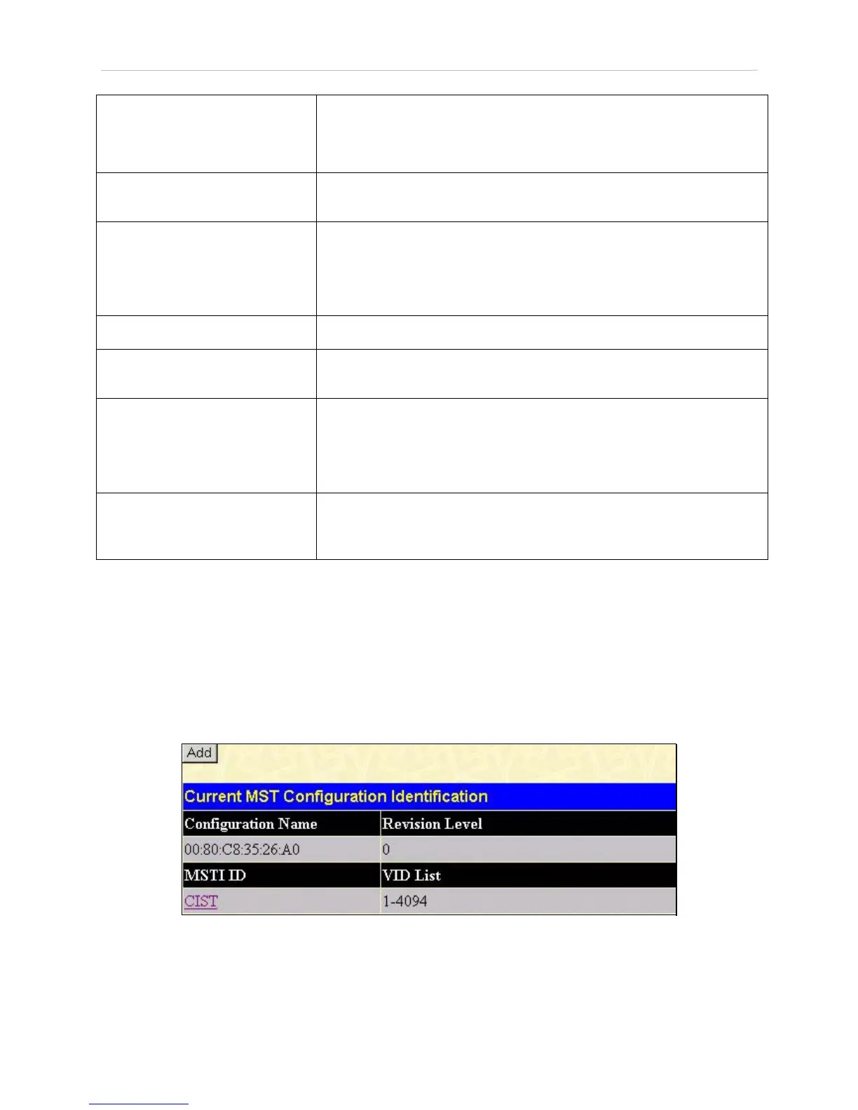
view the Current MST Configuration Identification window, click Configuration > Spanning
Tree > MST Configuration Table:
Figure 6- 21. Current MST Configuration Identification window
The window above contains the following information:
 Loading...