ENGLISH
63
10.4 - Motor shaft
The electronic control of the system ensures smooth starts so as to avoid excessive stress on the mechanical parts and thus prolong the life of
the product. In exceptional cases this characteristic could cause problems in starting the pump: after a period of inactivity, perhaps with the system
drained, the salts dissolved in the water could have settled and formed calcification between the moving part (motor shaft) and the fixed part of
the pump, thus increasing the resistance on starting. In this case it may be sufficient to help the motor shaft by hand to detach itself from the
calcifications. In this system the operation is possible because access to the motor shaft from outside is guaranteed and a groove is provided at
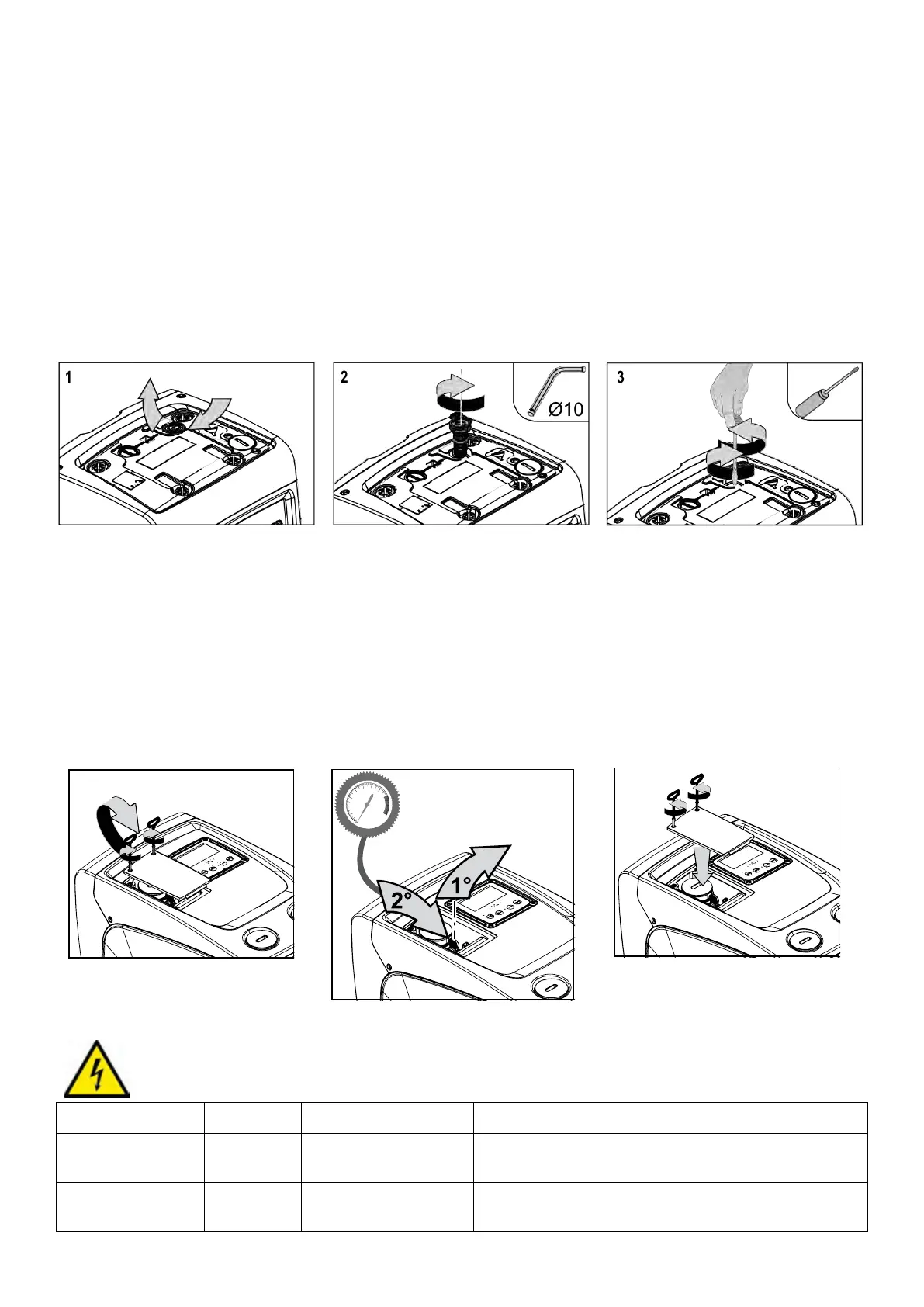
the end of the shaft. Proceed as follows:
1. remove the cover of the technical compartment (Fig.1 Face A);
2. lift the rubber cover of the motor shaft access cap (Fig. 23);
3. using a 10mm hexagonal key, remove the motor shaft access cap (Fig. 23);
4. insert a straight tip screwdriver in the groove on the motor shaft and manoeuvre, turning in 2 directions (Fig. 23);
5. if it is turning freely the system can be started, after having replaced the cap and cover that have been removed;
6. if rotation is blocked and it cannot be removed by hand, call the assistance service.
Figure 23
10.5 - Expansion Vessel
See paragraph 1.2 for the operations to check and adjust the air pressure in the expansion vessel and to replace it if it is broken.
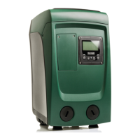
To access the valve of the expansion vessel, proceed as follows:
1. remove the access door to the special maintenance compartment (Fig.1 Face F) disengaging the 2 fixing screws with the accessory tool. It is
advisable not to remove the screws completely, so that you can used them to extract the door. Take care not to drop the screws inside the system
once you have removed the door (Fig. 24);
2. slip the rubber cap off the valve or the expansion vessel (Fig. 24);
3. regulate the valve as indicated in paragraph 1.2 (Fig. 24);
4. reposition the rubber cap (Fig. 24);
5. reposition the door and tighten the 2 screws (Fig. 24).
11. TROUBLESHOOTING
Before starting to look for faults it is necessary to disconnect the power supply to the pump (take the plug out of the socket).
Fault LED Probable Causes Remedies
The pump does not start.
White: off
No electric power. Check whether there is voltage in the socket and insert the plug again.
The pump does not start.
White: on
Shaft blocked. See paragraph 9.4 (motor shaft maintenance).