©
200324 2-7
General
PE ENGINE FUEL SYSTEM
CF65/75/85 series
4
5
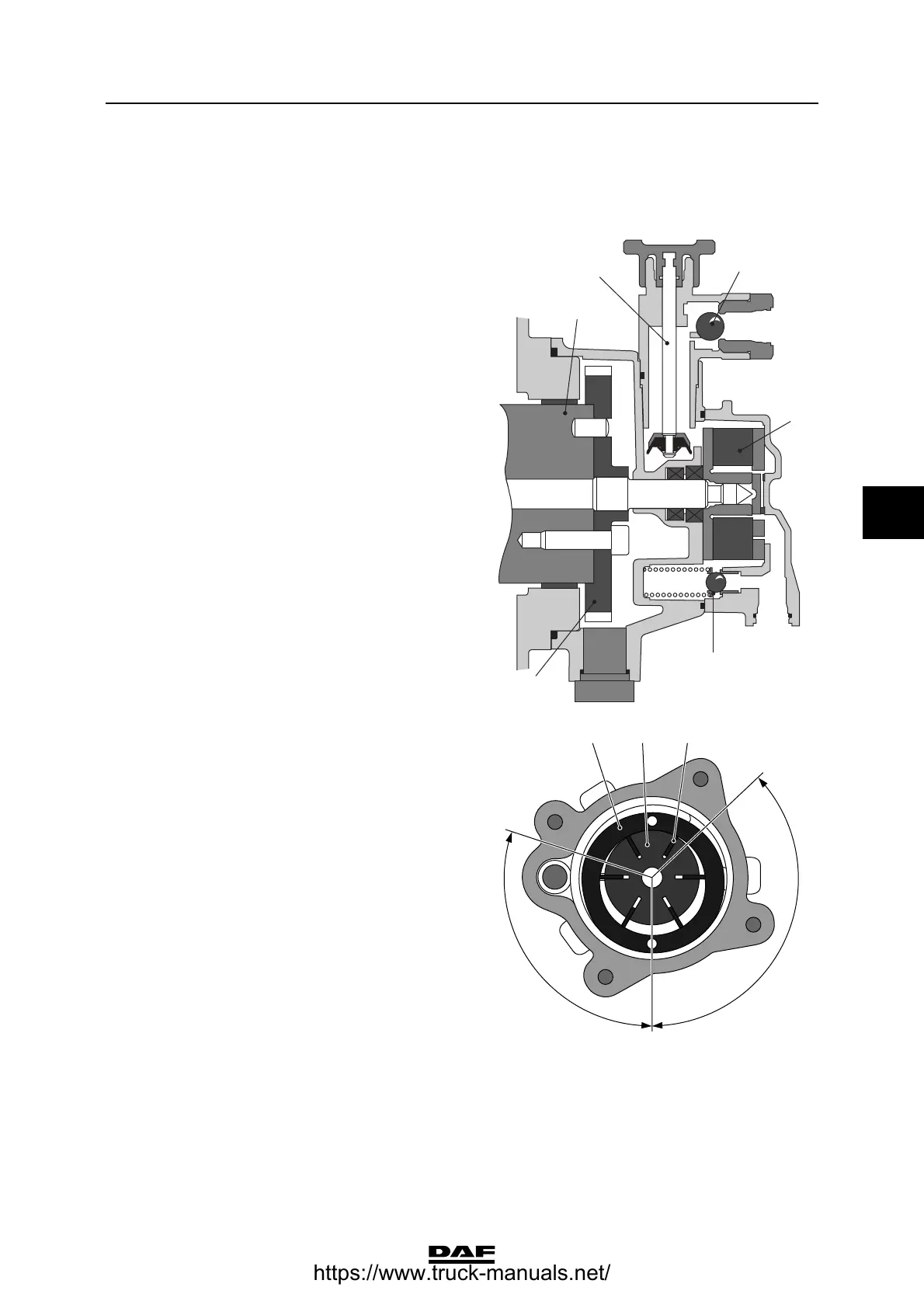
2.3 DESCRIPTION OF COMPONENTS
Fuel lift pump with integrated primer pump
The fuel lift pump with integrated primer pump is
fitted to the rear of the pump housing. The fuel lift
pump section (1) is driven via the pulse plate (3)
by the camshaft (4) in the pump housing.
The fuel lift pump (1) is a vane pump.
The vane pump consists of a stator (7) in which
the rotor (8) with the vanes (9) can be found. The
vanes (9) are forced against the surface of the
stator (7) by the centrifugal force and two
successive vanes form an enclosed space, the
pump chamber. Due to the elliptically-shaped
stator (7), with each revolution each pump
chamber undergoes a volume increase, the
suction stroke (angle A), a volume reduction and
the compression stroke (angle B).
To achieve a good seal, the rear of the vanes are
connected to the compression pipe of the pump.
This forces the vanes against the stator with
increased pressure, resulting in a good seal.
A pressure-relief valve (5) is fitted in the fuel lift
pump to protect the fuel system against
excessive fuel lift pump pressure caused by
excessive flow resistance.
I400428
3
5
1
6
2
4
i 400433
8 97
A
B
https://www.truck-manuals.net/
 Loading...