SQLC-214-097
4
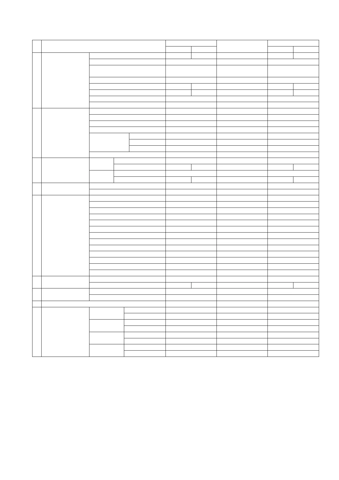
① Voltage, current input (2/2)
№ Setting item
3-phase 3-wire
Single-phase 3-wire
Single-phase
110V input 220V input 110V input 220V input
8 Measurement range
Voltage range 6600V 220V 110.0V 3300V 220V
Current range 100.0A 500A 50.0A
Current display peculiar
sensitivity
100.0A 500A 50.0A
Active power polarity One-side swing One-side swing One-side swing
Active power range 1200kW 40.0kW 100.0kW 150.0kW 10.00kW
Reactive power range 600kvar 20.00kvar 50.0kvar 75.0kvar 5.00kvar
Power-factor range LEAD 0.5‐1‐LAG 0.5 LEAD 0.5‐1‐LAG 0.5 LEAD 0.5‐1‐LAG 0.5
Frequency range 45‐65Hz 45‐65Hz 45‐65Hz
9
Analog output
(
2
)
Output factor 1 A(V) A(U) A
Output factor 2 V(UV) V(UN) V
Output factor 3 W W W
Output factor 4 cosφ cosφ cosφ
Output peculiar
sensitivity
Current 100.0% 100.0% 100.0%
Active power 100.0% 100.0% 100.0%
Reactive power 50.0% 50.0% 50.0%
Low input cut OFF OFF OFF
10
Pulse output
(
2
)
Output 1
Factor Wh Wh Wh
Pulse unit 10kWh/p 0.1kWh/p 1kWh/p 1kWh/p 0.1kWh/p
Output 2
Factor Wh Wh Wh
Pulse unit 10kWh/p 0.1kWh/p 1kWh/p 1kWh/p 0.1kWh/p
11
External operation
input (
2
)
Input 1 function Alarm reset Alarm reset Alarm reset
Input 2 function Max./Min. reset Max./Min. reset Max./Min. reset
12
Measurement display
ON/OFF
Voltage ON ON ON
Current ON ON ON
Active power ON ON ON
Reactive power ON ON ON
Power-factor ON ON ON
Frequency ON ON ON
Watt-hour of power receiving ON ON ON
Watt-hour of power transmission ON ON ON
var-hour of power receiving ON ON ON
var-hour of power transmission ON ON ON
Harmonic current ON ON ON
Harmonic voltage ON ON ON
Current leakage (
2
) ON ON ON
13 Input circuit
Phase line change (
4
) 3φ3W 1φ3W (U-N-W) 1φ2W
Input voltage (
5
) 110V 220V 300V 110V 220V
14 Measurement
Dead band 0.0% 0.0% 0.0%
Tidal current measurement General measurement General measurement General measurement
15 Analog output specification (
2
)(
3
) 1‐5V 1‐5V 1‐5V
16
Analog output
adjustment
(
2
)
Output 1
Bias adjustment 0.0% 0.0% 0.0%
Span adjustment 100.0% 100.0% 100.0%
Output 2
Bias adjustment 0.0% 0.0% 0.0%
Span adjustment 100.0% 100.0% 100.0%
Output 3
Bias adjustment 0.0% 0.0% 0.0%
Span adjustment 100.0% 100.0% 100.0%
Output 4
Bias adjustment 0.0% 0.0% 0.0%
Span adjustment 100.0% 100.0% 100.0%
Note(
2
) A setting item is not displayed in case there is no corresponding option.
The external operation input constitutes default value with an alarm-output option.
It becomes the next function in case there is no alarm-output option.
Input 1 function:Max. / Min. reset, Input 2 function:Measurement factor change.
Note(
3
) A setting item is not displayed if analog output is except DC0‐5V (or DC1‐5V) specification,
And analog output insulation product does not display a setting item.
Note(
4
) When the setting of phase line change of an input circuit is changed, it will return to the default value
of phase line which all set value changed.
Note(
5
) When phase line change setting of an input circuit is set as 3φ3W (or 1φ2W) and the input voltage
setting is changed, the voltage range returns to the default value of the phase line.
(For example:In case of 3φ3W, 6600V at the case of 110V setting, 300V at the case of 220V setting.)