SQLC-214-097
5
② Current input
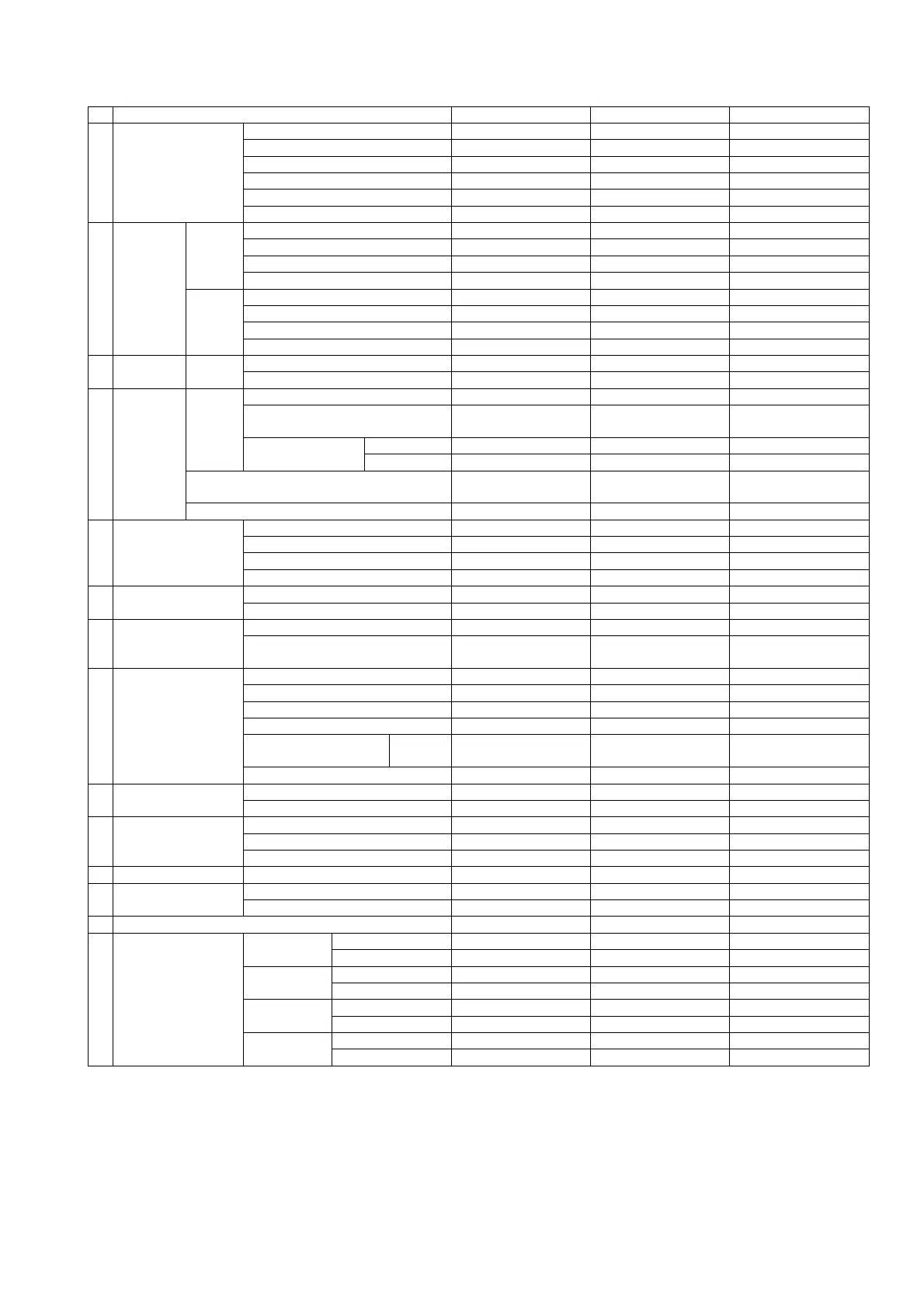
№ Setting item 3-phase 3-wire Single-phase 3-wire Single-phase
1 Display combination
Pattern Pattern 15 Pattern 15 Pattern 15
Main monitor A(V) A(U) A
Sub-monitor (Left) A(U) A(W) -
Sub-monitor (Center) A(W) A(N) -
Sub-monitor (Right) - - -
Bar graph A(V) A(U) A
2
Alarm
output
(
6
)
Alarm 1
Factor DA DA DA
Reset form AUTO AUTO AUTO
Contact delay time 0 second 0 second 0 second
Test - - -
Alarm 2
Factor DA DA DA
Reset form AUTO AUTO AUTO
Contact delay time 0 second 0 second 0 second
Test - - -
3
Demand
detection
Demand
current
Upper limit value 80.0A 400A 40.0A
Interval 0 second 0 second 0 second
4
Harmonic
detection
Current
Distortion-factor upper limit OFF OFF OFF
5th conversion content rate upper
limit
OFF OFF OFF
n-th content rate
Factor 5th 5th 5th
Upper limit OFF OFF OFF
5th conversion detection characteristics
Inverse-time-delay
mode
Inverse-time-delay
mode
Inverse-time-delay
mode
Average value time limit 0 minute 0 minute 0 minute
5
Leakage detection
(
6
)
Rated sensitivity current 0.1A 0.1A 0.1A
Factor switching Io Io Io
Circuit switching 1 phase earthing 1 phase earthing 1 phase earthing
Use ZCT selection Type 0 Type 0 Type 0
6 Backlight
Action AUTO AUTO AUTO
Brightness 3(Middle) 3(Middle) 3(Middle)
7 Measurement range
Current range 100.0A 500A 50.0A
Current display peculiar
sensitivity
100.0A 500A 50.0A
8
Analog output
(
6
)
Output factor 1 A(V) A(U) A
Output factor 2 A(U) A(W) -
Output factor 3 A(W) A(N) -
Output factor 4 - - -
Output peculiar
sensitivity
Current 100.0% 100.0% 100.0%
Low input cut OFF OFF OFF
9
External operation
input (
6
)
Input 1 function Alarm reset Alarm reset Alarm reset
Input 2 function Max./Min. reset Max./Min. reset Max./Min. reset
10
Measurement display
ON/OFF
Current ON ON ON
Harmonic current ON ON ON
Current leakage (
6
) ON ON ON
11 Input circuit Phase line change (
8
) 3φ3W 1φ3W (U-N-W) 1φ2W
12 Measurement
Dead band 0.0% 0.0% 0.0%
Tidal current measurement General measurement General measurement General measurement
13 Analog output specification (
6
)(
7
) 1‐5V 1‐5V 1‐5V
14
Analog output
adjustment
(
6
)
Output 1
Bias adjustment 0.0% 0.0% 0.0%
Span adjustment 100.0% 100.0% 100.0%
Output 2
Bias adjustment 0.0% 0.0% 0.0%
Span adjustment 100.0% 100.0% 100.0%
Output 3
Bias adjustment 0.0% 0.0% 0.0%
Span adjustment 100.0% 100.0% 100.0%
Output 4
Bias adjustment 0.0% 0.0% 0.0%
Span adjustment 100.0% 100.0% 100.0%
Note(
6
) A setting item is not displayed in case there is no corresponding option.
The external operation input constitutes default value with an alarm-output option.
It becomes the next function in case there is no alarm-output option.
Input 1 function:Max. / Min. reset, Input 2 function:Measurement factor change.
Note(
7
) A setting item is not displayed if analog output is except DC0-5V (or DC1-5V) specification,
And analog output insulation product does not display a setting item.
Note(
8
) When the setting of phase line change of an input circuit is changed, it will return to the default value
of phase line which all set value changed.