Si04-756 Removal of PCBs
Removal Procedure 27
6
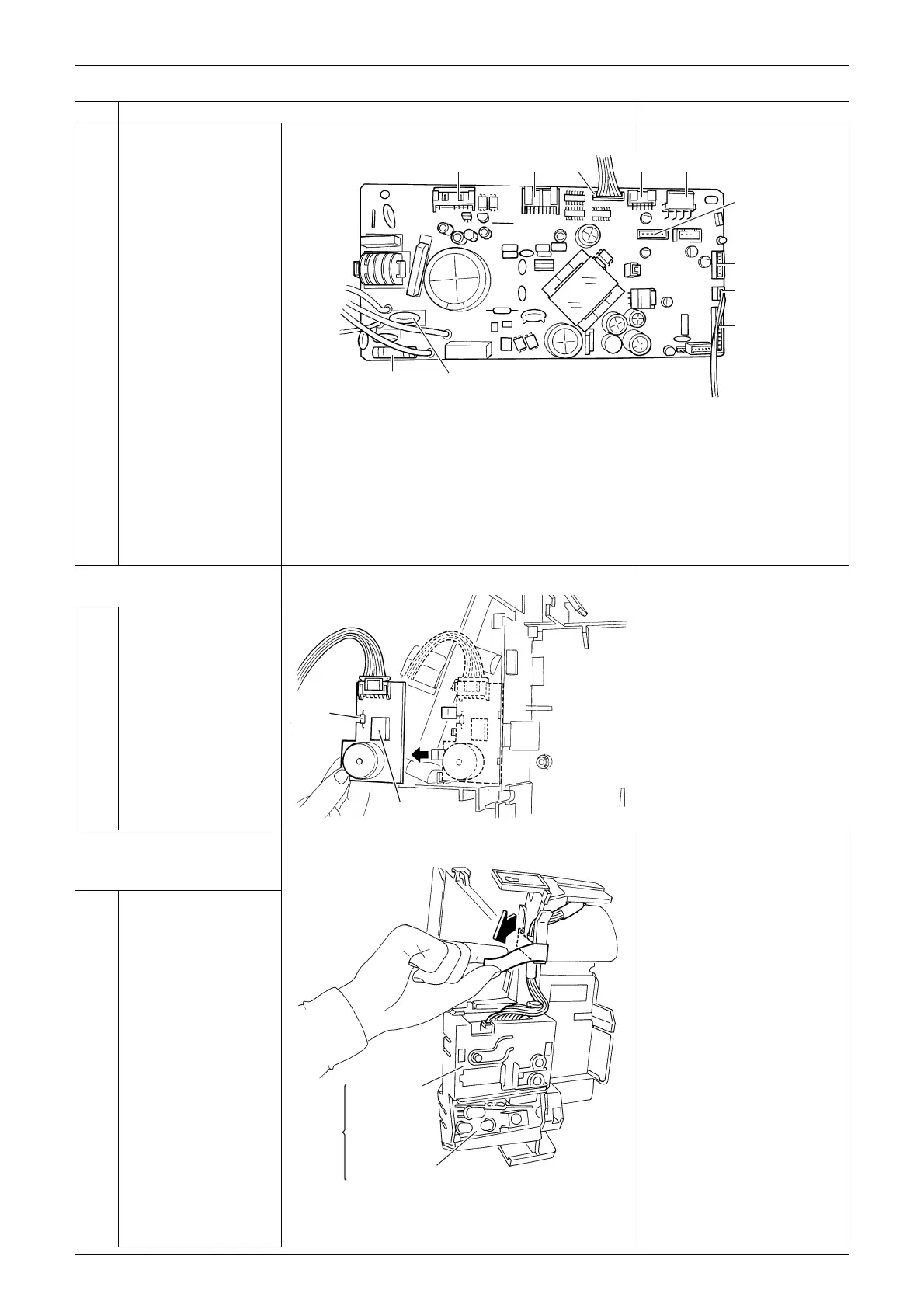
Names of parts of the
control PCB
[S1]: fan motor [S43]: dehumidifying
solenoid valve coils
[S21]: HA [S46]: display PCB
[S32]: indoor heat [S48]: humidity sensor
exchanger PCB
thermistor [S51]: reduction motor,
limit switch
[S41]: swing motors [S52]: streamer unit PCB
4. Remove the humidity
sensor PCB.
1
Unfasten the hook and
pull out the humidity
sensor PCB.
5. Remove the display PCB
and the signal receiver /
transmitter PCB.
1
Peel off the tape.
Step Procedure Points
[S1] [S41] [S52] [S43]
[S21]
[S48]
[S32]
[S46]
[S51]
(R14165)
Varistor
Fuse
3.15A, 250V
Humidify sensor
Room
temperature
thermistor
(R13963)
(R13964)
Display PCB
Signal receiver / transmitter PCB
Lamp
cover
assembly
 Loading...