IM 1227 • MODELS DC THERMOSTATS 18 www.DaikinApplied.com
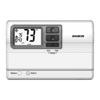
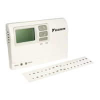
7-Day Programmable CommerCial DigiTal ThermosTaTs
Installation Instructions
Remove and Replace the Old Thermostat
To install the thermostat properly, please follow these step by
step instructions. If you are unsure about any of these steps,
call a qualied technician for assistance.
• Assemble tools: Flat blade screwdriver, wire cutters and
wire strippers.
• Make sure your Heater/Air Conditioner is working
properly before beginning installation of the thermostat.
• Carefully unpack the thermostat. Save the screws, any
brackets, and instructions.
• Turn off the power to the Heating/Air Conditioning system
at the main fuse panel. Most residential systems have a
separate breaker for disconnecting power to the furnace.
• Remove the cover of the old thermostat. If it does not
come off easily, check for screws.
• Loosen the screws holding the thermostat base or
subbase to the wall and lift away.
• Disconnect the wires from the old thermostat. Tape the
ends of the wires as you disconnect them, and mark them
with the letter of the terminal for easy reconnection to the
new thermostat.
• Keep the old thermostat for reference purposes, until your
new thermostat is functioning properly.
Wire Connections
If the terminal designations on your old thermostat do not
match those on the new thermostat, refer to the chart below or
the wiring diagrams that follow.
Table 4: Terminal Designations
Wire from the
old thermostat
terminal marked
Function
Install on the
new thermostat
connector marked
G or F Fan G
Y1, Y or C Cooling Y1
W1, W or H Heating W1/0/B
Rh, R, M, Vr, A Power R
C Common C
O/B Rev. Valve W1/O/B*
W2 2nd Stage Heat W2
Y2 2nd Stage Heat Y2
W3 3rd Stage Cooling W3
H, HUM Humidity HUM
D, DEHUM Dehumidity DEHUM
Ck1 Dry Contact Switch DRY CONTACT
CKGND Dry Contact Switch DRY CONTACT
S1, OUT - Outdoor Sensor OUTDOOR
S2, OUT + Outdoor Sensor OUTDOOR
AUX Auxilliary Output AUX
* O/B is used if your system is a Heat Pump
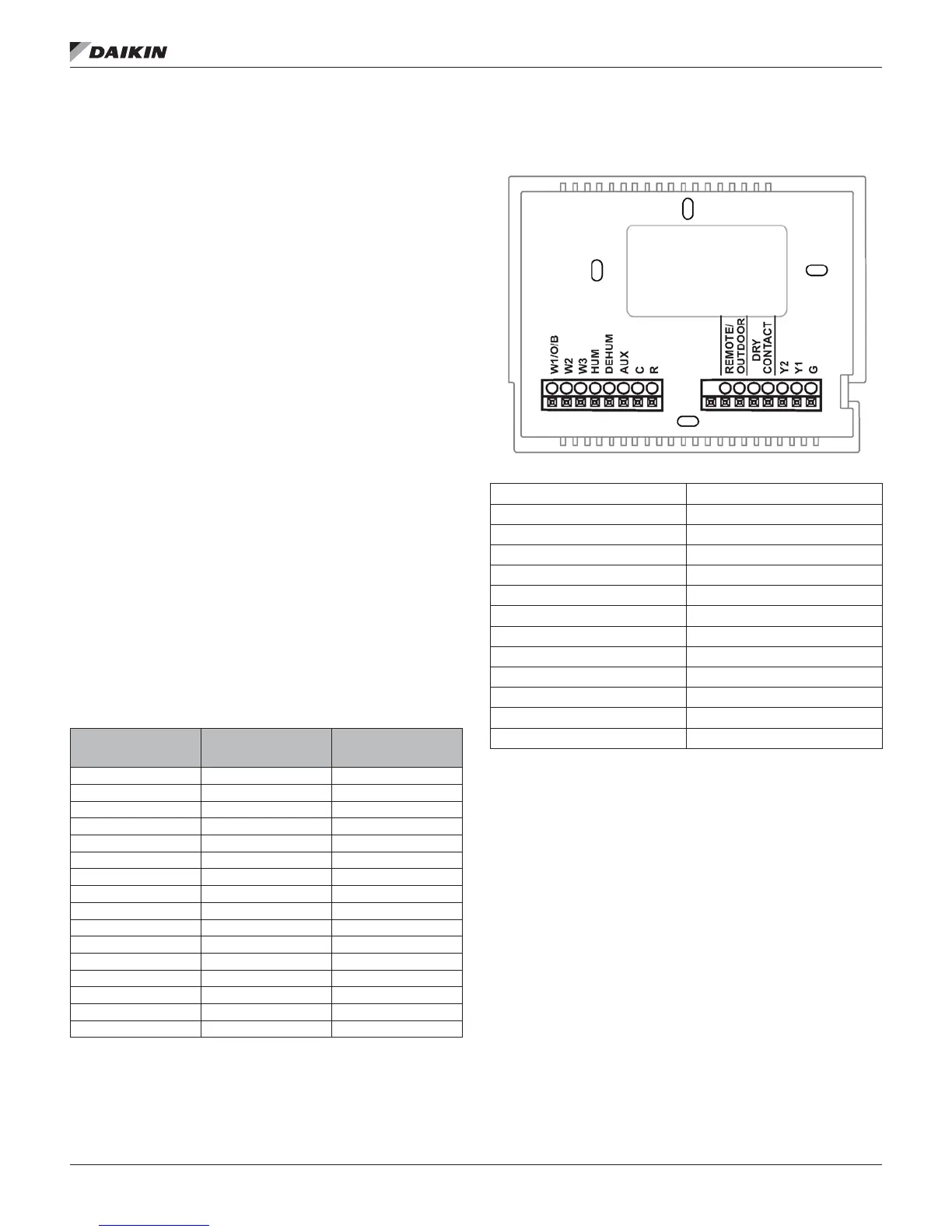
Figure 18: TSTATD4272C Thermostat Backplate
W1/O/B 1st stage heat/reversing valve
W2 2nd stage heat circuit
W3 3rd stage heat circuit
HUM Humidity control circuit
DEHUM Dehumidity control circuit
AUX Aux output
C 24 VAC common
R 24 VAC Return
OUTDOOR SENSOR Outdoor Sensor connections
DRY CONTACT Dry Contact connections
Y2 2nd stage compressor
Y1 1st stage compressor
G Fan relay
IMPORTANT: This thermostat requires both R (24 VAC Return)and C (24 VAC
Common) be connected to the backplate terminals.