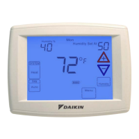
high resoluTion TouCh sCreen DigiTal ThermosTaT
www.DaikinApplied.com 59 IM 1227 • MODELS DC THERMOSTATS
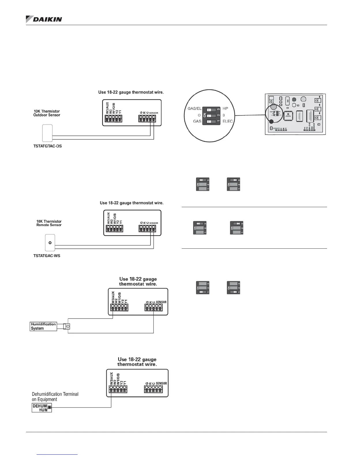
Wiring
Sensors
Outdoor Sensor: TSTATGTAC-OS Temperature Sensor 10K
ohm sensor at 77F/25C. Negative Temperature Coefcient.
Figure 58: TSTATGTAC-OS Temperature Sensor
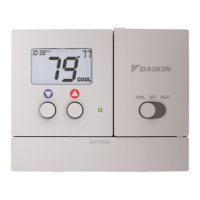
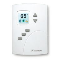
Indoor Remote Sensor with Override Button:TSTATGAC-WS
Temperature Sensor 10K ohm sensor at 77F/25C. Negative
Temperature Coefcient(see page 41 for sensor setup
instructions).
Figure 59: TSTATGAC-WS Temperature Sensor
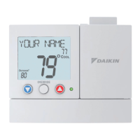
Figure 60: Humidication Setup
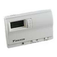
Figure 61: Dehumidication Setup
Explanation of Thermostat Dip Switches
Dip switches are located on the back of the thermostat
Figure 62: Dip Switch Location
GAS/EL HP GAS/EL HP
or
This dip switch congures the
thermostat to control a conventional
gas/electric system or a heat pump.
If your system is anything other than
a heat pump, leave this switch set for
GAS/EL.*
*For some commercial heat pumps,
this switch may need to be set for
GAS/EL. Consult the commercial heat
pump literature.
O
B
or
O
B
When the GAS/EL or HP dip switch
is congured for HP, this dip switch
(O or B) must be set to control the
appropriate reversing valve. If O is
chosen, the W1/O/B terminal will
energize in cooling. If B is chosen,
the W1/O/B terminal will energize in
heating.
or
GAS ELEC GAS ELEC
1. When GAS/EL or HP is set for
GAS/EL: This switch (GAS or
ELEC) controls how the thermostat
will control the Fan (G) terminal
in heating mode. When GAS is
chosen, the thermostat will not
energize the Fan (G) terminal in
heating. When ELEC is chosen the
thermostat will energize the fan in
heating.
2. When GAS/EL or HP is set for HP:
This switch (GAS or ELEC) denes
the Aux Heat type. When GAS is
chosen, the auxiliary heat will not
be allowed to run during heat pump
operation. When ELEC is chosen,
up to two stages of auxiliary strip
heat will be allowed to run.