Loop flushing relief valve
The loop flushing relief valve is incorporated into all H1 motors. Use the loop flushing option in
installations that require fluid to be removed from the low pressure side of the system circuit due to
cooling requirements.
The loop flushing relief valve is also used to facilitate the removal of contaminants from the loop.
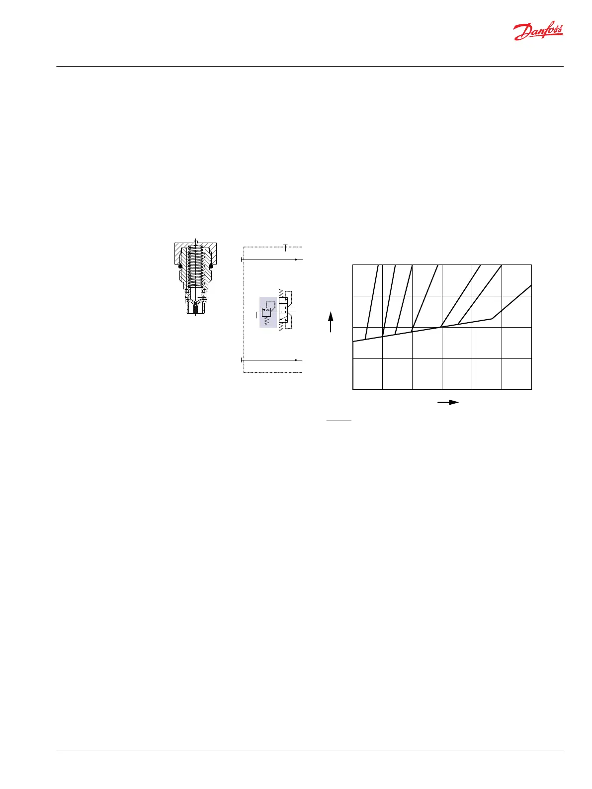
The loop flushing valve is equipped with an orificed charge pressure relief valve designed with a cracking
pressure of 16 bar [232 psi].
Valves are available with several orifice sizes to meet the flushing flow requirements of all system
operating conditions.
Loop flushing relief valve size
40 bar
30 bar
20 bar
10 bar
10 15 20 30 40
50
5
10 20 30 40 50 60
P006 034
0
X
Y
Legend:
X Loop flushing flow (l/min)
Y Low system pressure minus case pressure (bar)
Displacement limiter
All Series H1 motors incorporate mechanical displacement limiters.
The minimum displacement of the motor is preset at the factory with a set screw in the motor housing.
A tamper-proof cap is provided.
Technical Information
H1 Bent Axis Variable Displacement Motors, Size 060/080/110/160/210/250
Operation
©
Danfoss | December 2016 11037153 | BC00000043en-US1103 | 21

 Loading...


