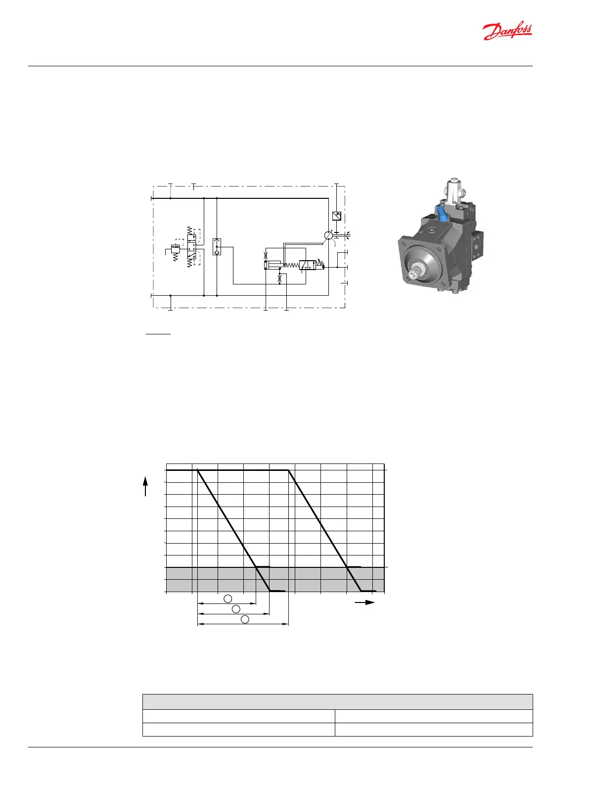
Option LHBA – hydraulic proportional control
LH – hydraulic proportional non-pressurized = max. displacement
BA – without Pressure Compensator Over Ride / without Brake Pressure Defeat
Hydraulic schematic
n
P005901
B
A
N
M4
M5
L2
L1
X1
X1
MA
MB
min
max
Where:
A, B Main pressure lines
L1, L2 Drain lines
M4, M5 Gauge port servo pressure
MA, MB Gauge port system pressure
X1 Control pressure port
N Speed sensor (optional)
Option LHBA
Hydraulic actuator X1
Non-pressurized = max. displacement.
Full-pressurized = min. displacement.
Displacement (%) versus Input command (bar)
LH
LH
P005 902
0%
20%
40%
60%
80%
100%
32°
6°
1
2
bar
3
1 = Control ramp, 100% - 20% (14 bar [203 psi])
2 = Control ramp, 100% - 0% (17.5 bar [254 psi])
3 = Control start setting range
Grey area = Intended to be used for zero degree capability.
Control start setting range (pressure above case pressure)
p
start
(possible settings per MMC.- adjustable) 2 to 30 bar [29 to 435 psi]
P
max allowable
Control start setting + 50 bar [725 psi]
Technical Information
H1 Bent Axis Variable Displacement Motors, Size 060/080/110/160/210/250
Controls – nomenclature, description
68 |
©
Danfoss | December 2016 11037153 | BC00000043en-US1103

 Loading...


