Options L1BA, L2BA – electric proportional control
L1 – electric proportional 12 V / de-energized = max. displacement
BA – without Pressure Compensator Over Ride / without Brake Pressure Defeat
L2 – electric proportional 24 V / de-energized = max. displacement
BA – without Pressure Compensator Over Ride / without Brake Pressure Defeat
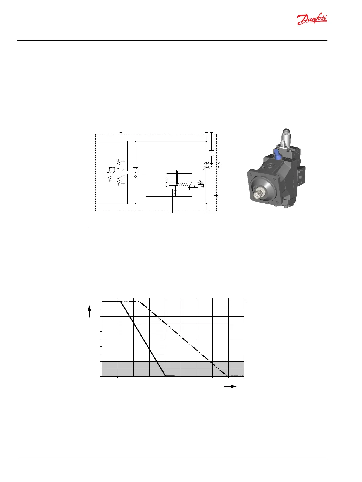
Hydraulic schematic
A
B
n
min
max
C1
M4
M5 MB
L1
L2
N
P003426
MA
Where:
A, B Main pressure lines
L1, L2 Drain lines
M4, M5 Gauge port servo pressure
MA, MB Gauge port system pressure
N Speed sensor (optional)
Options L1BA, L2BA
Solenoid C1
De-energized = max. displacement
Full-energized = min. displacement
Displacement (%) versus Input Command (mA)
0 200 400 600 800 1000 1200 1400 1600 1800
mA
L2 L1
32°
6°
P003 483
0%
20%
40%
60%
80%
100%
L1, L2 = L1, L2 Control
Grey area = Intended to be used for zero degree capability.
Below are formulas to calculate start and end input command dependent on displacements:
Technical Information
H1 Bent Axis Variable Displacement Motors, Size 060/080/110/160/210/250
Controls – nomenclature, description
42 |
©
Danfoss | December 2016 11037153 | BC00000043en-US1103

 Loading...


