Options E1AA, E2AA – electric two-position control
E1 – electric two-position 12 V / de-energized = max. displacement
E2 – electric two-position 24 V / de-energized = max. displacement
AA– without Pressure Compensator Over Ride / without Brake Pressure Defeat
A
B
max
min
C6
M4
M5 MB
L1
L2
N
P003430
n
MA
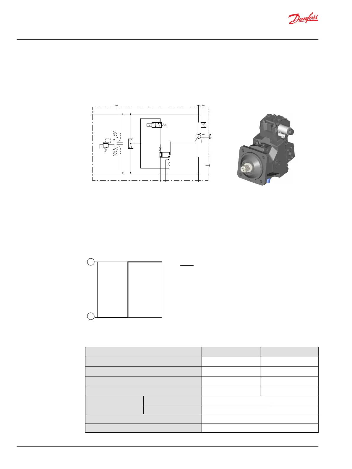
A, B Main pressure lines
L1, L2 Drain lines
M4, M5 Gauge port servo pressure
MA, MB Gauge port system pressure
N Speed sensor (optional)
Options E1AA, E2AA
Solenoid C6
De-energized = max. displacement
Energized = min. displacement
Displacement versus control signal
Where:
1 Minimum displacement
2 Maximum displacement
Two-position solenoid data C6
Description 12 V 24 V
Min. supply voltage
9.5 V
DC
19 V
DC
Max. supply voltage (continuous)
14.6 V
DC
29 V
DC
Nominal coil resistance @ 20 °C [68 °F]
8.4 Ω 34.5 Ω
Recommended input current
1050 mA 500 mA
IP Rating
IEC 60 529
IP 67
DIN 40 050, part 9
IP 69K with mating connector
Bi-directional diode
yes
Connector color
Blue
Technical Information
H1 Bent Axis Variable Displacement Motors, Size 060/080/110/160/210/250
Controls – nomenclature, description
54 |
©
Danfoss | December 2016 11037153 | BC00000043en-US1103

 Loading...


