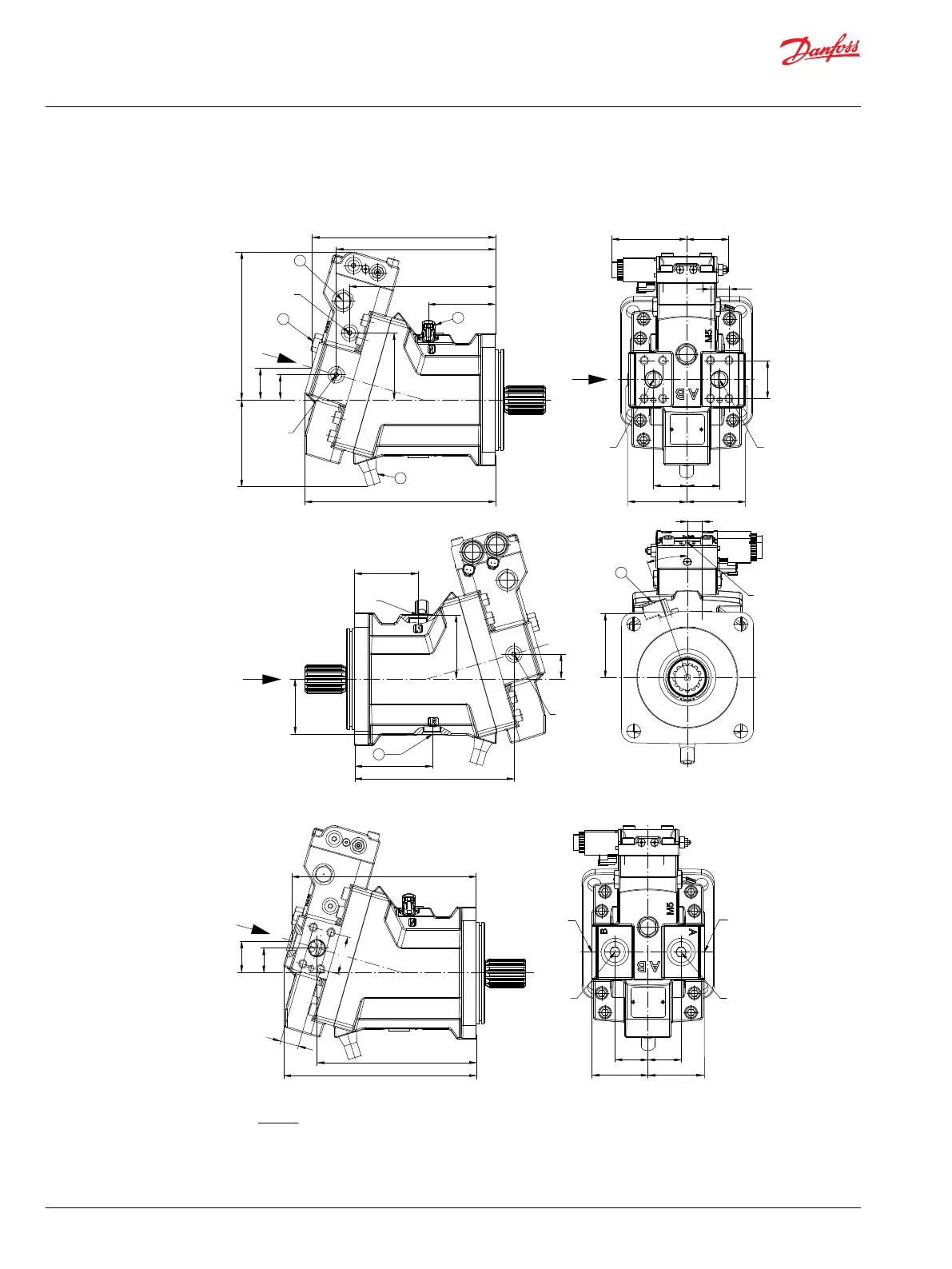
SAE flange design – options T* D* and P* D* (two-position control, PCOR, electric BPD)
Axial ports
W
X
Y
AA
BA
CA
BD
BA
CF
CJ
AD
BC
CC CC
CH
BC
AE
CE
ACAB
BB
CB
BE
CD
BB
CK
CG
Y
W
X
CL
α
CM
P006 041
3
3
1
4
2
B
M4
M5
MA
MB
L1
L2
6
A
Radial ports
P006 042
AF
Z
Z
BH
CN
CO
BJ
BL
BM
CP
BK BK
CP
B
A
MA
MB
Legend:
1 Loop flushing relief valve
2 Loop flushing shuttle spool
3 Speed sensor
4 Minimum angle stop adjustment
5 Connector: DT04-2P
6 Alternate position of case drain port
Technical Information
H1 Bent Axis Variable Displacement Motors, Size 060/080/110/160/210/250
Dimensions
94 |
©
Danfoss | December 2016 11037153 | BC00000043en-US1103

 Loading...


