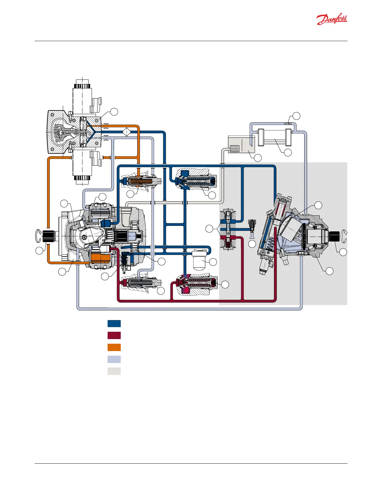
H1 pictorial diagram
P003 423
2
3
6
7
4
10
8
9
16
15
14
13
12
11
17
5
7
18
1
5
Working loop A (Low pressure) and charge pressure
Working loop B (High pressure)
Servo pressure
Case drain
Suction
1. Bent Axis Variable Displacement Motor
2. Axial Piston Variable Displacement Pump
3. Electric Displacement Control (EDC)
4. Charge Pump
5. Charge Check / High Pressure Relief Valve
6. Loop Flushing Valve
7. Pressure Limiter Valve
8. Charge Pressure Relief Valve
9. Servo Cylinder
10. Charge Pressure Filter
11. Heat Exchanger
12. Heat Exchanger Bypass Valve
13. Valve Segment
14. Pump Swashplate
15. Input Shaft
16. Output Shaft
17. Reservoir
18. to Motor Case
Technical Information
H1 Bent Axis Variable Displacement Motors, Size 060/080/110/160/210/250
H1 general information
©
Danfoss | December 2016 11037153 | BC00000043en-US1103 | 9

 Loading...


